Transformer looped network structure fault control method

A fault control and transformer technology, applied in AC network circuits, electrical components, circuit devices, etc., can solve problems such as the inability to meet the friendly access of large-scale distributed energy sources, the inability to meet high-sensitivity loads, and the impact on power supply reliability. Achieve the effect of eliminating overload risk, improving equipment utilization, and improving power supply reliability

Pending Publication Date: 2020-06-16
STATE GRID CORP OF CHINA +1
View PDF0 Cites 0 Cited by
  • Summary
  • Abstract
  • Description
  • Claims
  • Application Information

AI Technical Summary

Problems solved by technology

Open-loop operation not only affects the further improvement of power supply reliability, but also cannot meet the friendly access of large-scale distributed energy
[0003] In the prior art, there is a ring-network-closing grid system based on the distribution automation terminal, which realizes the closed-loop operation of the distribution network. However, when a fault occurs, although the power supply can be transferred through the tie line, there is still a second-level delay. Power failure occurs, which cannot meet the needs of high-sensitivity loads such as precision processing and semiconductor manufacturing enterprises
And with the development of distributed energy, this system cannot meet the friendly access of large-scale distributed energy
In the prior art, there is a lack of a distribution network architecture that facilitates the closed-loop operation of multiple AC lines and flexible power control. When a fault occurs, the load can be quickly transferred by switching the operation mode to improve the reliability of power supply.

Method used


Image

  • Transformer looped network structure fault control method

Examples


Embodiment Construction

[0014] Embodiments of the present invention are described in detail below, examples of which are shown in the drawings, wherein the same or similar reference numerals denote the same or similar elements or elements having the same or similar functions throughout. The embodiments described below by referring to the figures are exemplary only for explaining the present invention and should not be construed as limiting the present invention.

[0015] Below in conjunction with accompanying drawing, technical scheme of the present invention is described in further detail:

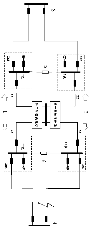
[0016] The structural representation of figure of the present invention is as figure 1 Shown, described a kind of transformer ring network structure fault control method, described system comprises the ring network frame of two petal type wiring, wherein the ring network frame of a petal type connection comprises A substation busbar, I section busbar in A substation and the ring formed by section I busbar in di...


PUM


Abstract

The invention discloses a transformer looped network structure fault control method. The method comprises two petal type wiring looped network racks. One petal type wiring looped network rack comprises a loop formed by a transformer substation bus A, a bus section I in the power distribution station A and a bus section I in a power distribution station B; the bus section I in the power distribution station A and the bus section I in the power distribution station B are provided with first bus tie switches. The other petal type wiring looped network rack comprises a loop formed by a substationbus B, a bus section II in the power distribution station A and a bus section II in the power distribution station B; and the bus section II in the power distribution station A and the bus section IIin the power distribution station B are provided with second bus tie switches; and the petals of the petal type wiring looped network racks are connected with one another through a first system converter and a second system converter which are connected with each other. The architecture disclosed by the invention can coordinate loads, eliminate heavy load risks, improve an equipment utilization rate and improve power supply reliability.

Description

technical field [0001] The invention discloses a fault control method for a transformer ring network structure, and relates to the technical field of hybrid AC and DC distribution network architecture. Background technique [0002] The rural power distribution network is connected to the main grid of the grid, and the electricity used by thousands of households in rural areas is not only a key technology for connecting the main grid, various users and distributed energy, but also an important part of building a strong smart grid. The operation control of the 10kV distribution network is relatively simple. Although the 10kV distribution network adopts the ring network connection mode, most of them are single-radiation open-loop operation. With the development of economy and society and the gradual advancement of smart grid, the disadvantages of open-loop operation are gradually becoming prominent. Open-loop operation not only affects the further improvement of power supply r...

Claims


Application Information

Patent Timeline
IPC IPC(8): H02J3/00
CPCH02J3/00
Inventor 王海宁王太峰江晨苏昕高强王海露肖茜黄琴丽赵金艳
Owner STATE GRID CORP OF CHINA
Why Eureka
Try Eureka