
Tube-type approximation and imaging unit mechanical tandem type scanning tunneling microscope body

An imaging unit and scanning tunneling technology, which is applied in the field of scanning probe microscopes, can solve the problems of high vibration intensity, loss of atomic-level imaging, and no low temperature conditions, etc., and achieve low starting voltage, simple structure, and strong rigidity.

Pending Publication Date: 2020-06-16
HEFEI INSTITUTES OF PHYSICAL SCIENCE - CHINESE ACAD OF SCI
View PDF1 Cites 2 Cited by
  • Summary
  • Abstract
  • Description
  • Claims
  • Application Information

AI Technical Summary

Problems solved by technology

For example, a water-cooled magnet or even a hybrid magnet is used to obtain a magnetic field above 40T, but the room temperature aperture provided by the magnet does not exceed 50 mm. In order to obtain low-temperature test conditions, a cryostat needs to be implanted in it, which further reduces the available space of the sample chamber.
In addition, the vibration intensity of water-cooled magnets (including hybrid magnets) is high, and the magnetic field ripple is much higher than that of traditional superconducting magnets, which increases the difficulty of STM design
At present, only two attempts have been reported internationally (Nano Research 8, 3898 (2015); Rev. Sci. Instrum. 88, 093706 (2017)), but they all have shortcomings: for example, the work of Meng et al. Atomic-level imaging at 27T, but did not introduce low-temperature conditions; although Tao et al. provided low-temperature test conditions, the atomic-level imaging was lost when the magnetic field increased to about 5T
[0004] Invention patent "Multi-Zone Driven Inertial Piezoelectric Motor Device and Scanning Probe Microscope and Control Method" (Patent No.: 201410209747.8) proposes a radially space-compatible inertial piezoelectric motor device and scanning probe microscope, in order to ensure The stepping stability of the motor under low temperature conditions requires that the length of the piezoelectric body group be large enough. The advantage of this design is to achieve a large-scale scanning of tens of microns, but it is difficult to achieve atomic-level imaging because the probe-sample circuit is not compact enough.

Method used


Image

  • Tube-type approximation and imaging unit mechanical tandem type scanning tunneling microscope body
  • Tube-type approximation and imaging unit mechanical tandem type scanning tunneling microscope body
  • Tube-type approximation and imaging unit mechanical tandem type scanning tunneling microscope body

Examples


Embodiment 1

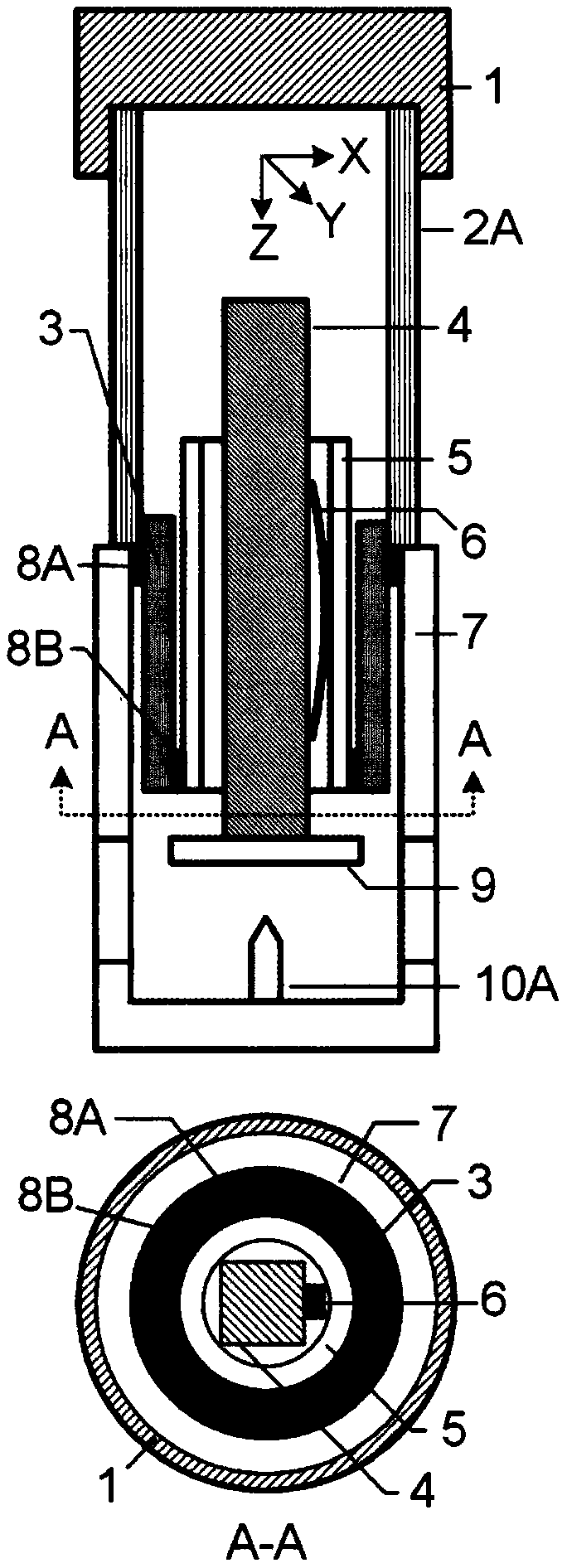
[0028] Embodiment 1: See for details figure 1 , a tubular approaching and imaging unit mechanical tandem scanning tunneling microscope mirror body, including a base 1, a slide bar 4, a sleeve 5 and a spring leaf 6, and is characterized in that it also includes a first piezoelectric tube 2A, a second piezoelectric tube An electric tube 3 and a probe holder 7, one end of the first piezoelectric tube 2A is fixed on the base 1, and the other end is a free end for deformation, and one end of the second piezoelectric tube 3 is in common with the free end of the first piezoelectric tube 2A. The shaft is fixed, the other end of the second piezoelectric tube 3 is a free end for deformation, the second piezoelectric tube 3 is a four-quadrant split piezoelectric tube, and the sleeve 5 is fixed concentrically and coaxially on the second piezoelectric tube 3 Deformation of the free end, the spring piece 6 exerts pressure along the radial direction of the casing 5 to elastically clamp the s...

Embodiment 2

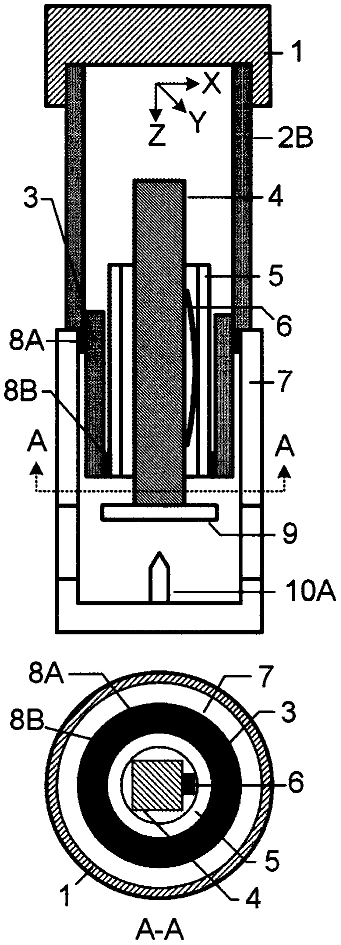
[0029] Embodiment 2: See for details figure 2 , a tubular approaching and imaging unit mechanical tandem scanning tunneling microscope mirror body, characterized in that: the first piezoelectric tube 2A external electrode is 2B of XYZ piezoelectric tubes arranged in four quadrants along the axial direction, the second piezoelectric tube The tube 3 and the first piezoelectric tube 2B are also arranged in four quadrants with external electrodes, and the external electrodes can be short-circuited one by one in the axial direction and share electrodes, thereby effectively reducing control signals and control lines.

Embodiment 3

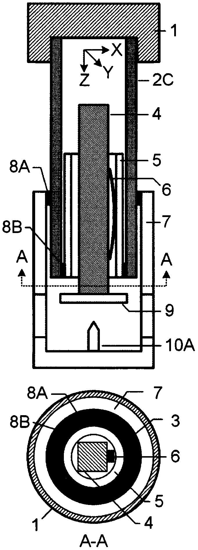
[0030] Embodiment 3: See for details image 3 , a tubular approximation and imaging unit mechanical tandem scanning tunneling microscope mirror body, characterized in that: the first piezoelectric tube 2B and the second piezoelectric tube 2C are integrally arranged to simplify the mirror body structure.


PUM


Abstract

The invention relates to a tube-type approximation and imaging unit mechanical tandem type scanning tunneling microscope body. The tube-type approximation and imaging unit mechanical tandem type scanning tunneling microscope body comprises a base, a sliding rod, a sleeve and a spring piece, and is characterized by further comprising a first piezoelectric tube, a second piezoelectric tube and a probe bracket, wherein one end of the first piezoelectric tube is fixed on the base, and the other end is connected and fixed to the second piezoelectric tube in a tandem manner in the axial direction; the sleeve is concentrically and coaxially fixed to the deformation free end of the second piezoelectric tube; the spring piece exerts pressure in the radial direction of the sleeve to clamp the sliding rod to the inner wall of the guide rail; the sliding direction of the sliding rod is in the axial direction of the sleeve; and the probe bracket and the second piezoelectric tube are concentricallyand coaxially arranged, and one end of the probe bracket is fixed to a tandem connection position of the first piezoelectric tube and the second piezoelectric tube. The tube-type approximation and imaging unit mechanical tandem type scanning tunneling microscope body is highly compact in radial and axial structures, the second piezoelectric tube is further used for approximating low starting voltage capable of realizing a needle sample approximation step, high rigidity of the scanning unit is ensured, the main body is made of an insulating material, the cross section of the structure is free of a conductive loop, and the tube-type approximation and imaging unit mechanical tandem type scanning tunneling microscope body is particularly suitable for extreme physical conditions of extremely low temperature, strong / fast changing magnetic field and strong vibration.

Description

technical field [0001] The invention discloses a tube-shaped approximation and imaging unit mechanical series scanning tunneling microscope mirror body, which belongs to the technical field of scanning probe microscopes, and in particular relates to scanning tunneling microscopes. Background technique [0002] Scanning Tunneling Microscopy (STM) can provide information on electronic state distribution and energy band structure on the surface of materials at the atomic scale, and is a powerful characterization method in the fields of condensed matter physics and materials (Rev.Mod.Phys.79(2007)353-419 ). The core component of STM is the mirror body, which directly determines the resolution performance of the microscopic representation of the STM system, and also determines the complexity of the system that the STM can integrate. The most common STM system integration conditions include ultra-high vacuum at room temperature, solution, and low-temperature strong magnetic field...

Claims


Application Information

Patent Timeline
IPC IPC(8): G01Q60/14G01Q60/16
CPCG01Q60/14G01Q60/16
Inventor 孟文杰赵科森侯玉斌陆轻铀
Owner HEFEI INSTITUTES OF PHYSICAL SCIENCE - CHINESE ACAD OF SCI
Learn More