
Method for detecting quality of conductive tube based on relative motion

A relative motion, conductive tube technology, applied in measuring devices, material analysis by electromagnetic means, instruments, etc., can solve problems such as inapplicability, not involving information collection and analysis, and limitations.

Inactive Publication Date: 2020-06-16
CENT SOUTH UNIV
View PDF10 Cites 2 Cited by
  • Summary
  • Abstract
  • Description
  • Claims
  • Application Information

AI Technical Summary

Problems solved by technology

At present, the most widely used online detection methods for conductive pipe rod defects are: eddy current detection method and image-based surface quality detection method, but both have application limitations: the former is sensitive to defects such as cracks, scratches, inclusions, pits and other defects on the product surface High, but this method must have enough time to heat to fully expose the defect, the response speed is slow, and it is not suitable for application in high-speed production lines; Pipe sticks cannot be detected
The above methods are all limited by their respective principles, and the production process often involves high-temperature treatment methods such as annealing. The above-mentioned testing facilities cannot be installed throughout the production line, and there are "blind spots" in testing and control.
Patent CN201310530795.2 discloses a resistance testing device, which can measure the resistance change of samples in a variable temperature environment, but the patent does not involve information collection and analysis, and the measured area is fixed

Method used


Image

  • Method for detecting quality of conductive tube based on relative motion
  • Method for detecting quality of conductive tube based on relative motion
  • Method for detecting quality of conductive tube based on relative motion

Examples


Embodiment 1

[0061] Testing material: T2 red copper rod, diameter 7.92mm, length 305mm, Figure 6 Photos of samples for testing;

[0062] Binding post interval / information collection area length: 30mm;

[0063] Input constant current: 1.3A;

[0064] Movement mode: the detection device is stationary, and the sample moves;

[0065] Sample movement speed: 30mm / s;

[0066] Signal acquisition frequency: 20 times / s;

[0067] Standard conductivity: 99.8%IACS;

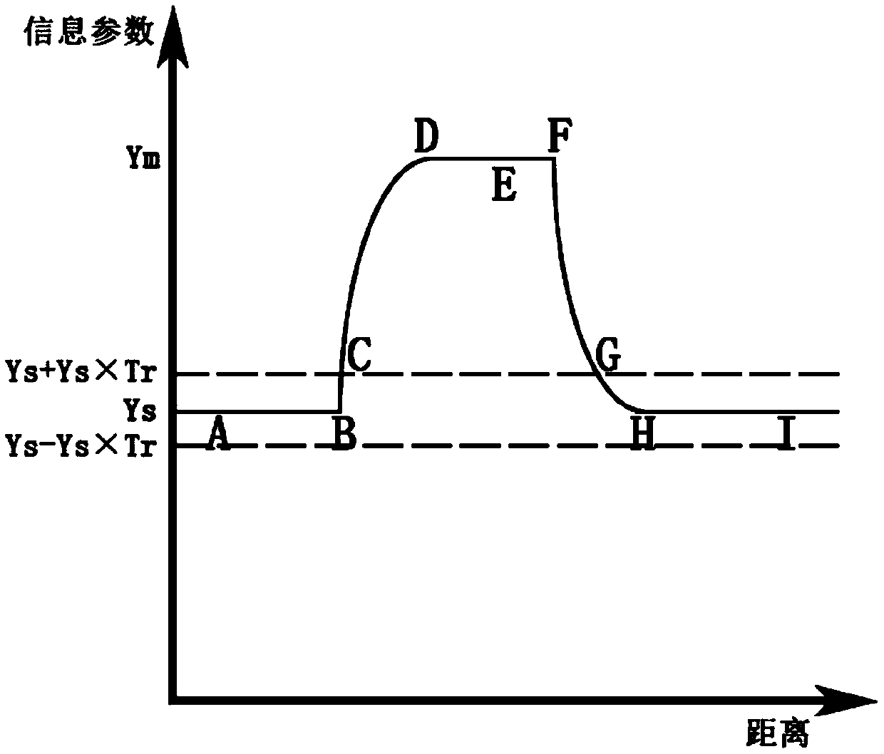
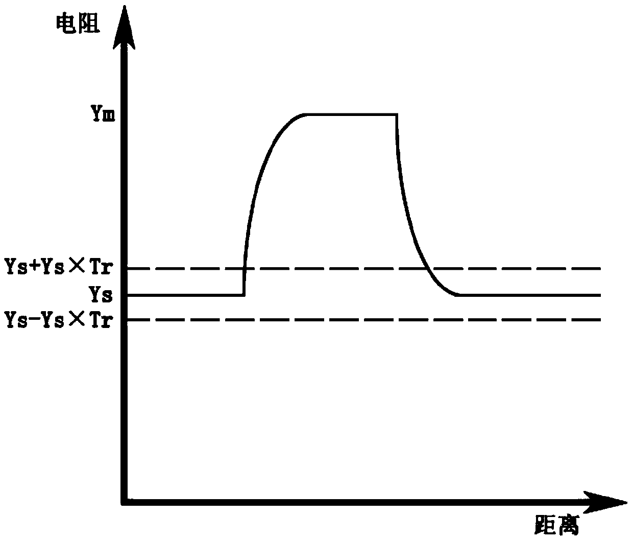
[0068] Figure 7 is the obtained conductivity-distance curve, T r =0.003, according to |actual conductivity-standard conductivity| / standard conductivityr , it is judged that there is no defect, and the sample is qualified.

Embodiment 2

[0070] Detection material: stainless steel pipe, outer diameter 20mm, inner diameter 18mm, length about 23cm, Figure 8 Photos of samples for testing;

[0071] Binding post interval / information collection area length: 50mm;

[0072] Input constant current: 2.3A;

[0073] Movement mode: the detection device is stationary, and the sample moves;

[0074] Sample movement speed: 30mm / s;

[0075] Signal collection frequency: 30 times / s;

[0076] Standard conductivity: 0.139MS / m;

[0077] Figure 9 is the obtained conductivity-distance curve, T r =0.0144, according to |actual conductivity-standard conductivity| / standard conductivity≥T r , it is determined that there are 2 defects. The conductivity drops abnormally within the range of 19mm-20mm, corresponding to the first defect entering the information collection area, Y m1 =0.132mMS / m, the electrical conductivity within the position range of 69mm-70mm returns to normal, and the corresponding defect leaves the information co...

Embodiment 3

[0080] Testing material: aluminum alloy bar, diameter 5mm, length 800mm;

[0081] Binding post interval / information collection area length: 100mm;

[0082] Input constant current: 1.0A;

[0083] Movement mode: the detection device is stationary, and the sample moves;

[0084] Sample movement speed: 30mm / s;

[0085] Signal acquisition frequency: 60 times / s;

[0086] Standard voltage: 0.14418mV;

[0087] Figure 11 is the obtained voltage-distance curve, T r =0.001645, according to|actually measured voltage signal-standard voltage signal| / standard voltage signal≥T r , it is determined that there is 1 defect. The voltage rises abnormally within the range of 310mm-364mm, and the corresponding defect enters the information collection area, Y m =0.14635mV, the voltage within the range of 410mm-464mm returns to normal, the corresponding defect leaves the information collection area, the distances between the start point and end point of the defect and the start point of infor...


PUM

PropertyMeasurementUnit
Cross-sectional areaaaaaaaaaaa
Diameteraaaaaaaaaa
Movement speedaaaaaaaaaa

Abstract

The invention relates to a method for detecting the quality of a conductive tube rod based on relative motion, and belongs to the technical field of material quality detection. The method comprises the following steps that: during detection, a detection device and a conductive tube rod can move relatively, and the quality of the conductive tube rod is judged by continuously collecting informationand calculating information parameters, wherein the information comprises but is not limited to a voltage, a current and a position, and the information is continuous information and the information parameters are selected from one or more of the voltage, resistance, resistivity, conductivity and electrical conductivity; obtained actual information parameters are compared with standard informationparameters; when a result obtained by dividing the absolute value of the difference of the actual information parameter and the standard information parameter by the standard information parameter isgreater than or equal to a defect judgment threshold value, a defect is determined to exist in the region corresponding to the actual information parameter; and when the result obtained by dividing the absolute value of the difference of the actual information parameter and the standard information parameter by the standard information parameter is smaller than a defect judgment threshold, the quality of the region corresponding to the actual information parameter is determined to be qualified.

Description

technical field [0001] The invention relates to a method for detecting the quality of a conductive pipe rod based on relative motion, which belongs to the technical field of material quality detection, and specifically belongs to the technical field of continuous material quality detection. Background technique [0002] With the development of the national economy, the production capacity of conductive pipe rods in my country has been continuously expanded, and the production categories have been continuously expanded. However, due to the lack of an effective online detection and monitoring system, the quality of the produced conductive pipe rods is not guaranteed, which makes my country lack of competitiveness in the high-end field of conductive pipe rod production. Establishing an on-line detection system for defects in the production process of conductive pipe rods, and improving product quality through accurate feedback and control of the production process have always b...

Claims


Application Information

Patent Timeline
IPC IPC(8): G01N27/04G01N27/00
CPCG01N27/00G01N27/041
Inventor 李红英赵辉
Owner CENT SOUTH UNIV
Learn More