Medical image imaging device
An imaging equipment and medical imaging technology, applied in medical science, instruments for radiological diagnosis, diagnosis, etc., can solve the problems of cross-infection, high cost and difficulty of imaging equipment, reduce pollution, facilitate rapid disinfection and use, reduce the effect of interference
- Summary
- Abstract
- Description
- Claims
- Application Information
AI Technical Summary
Problems solved by technology
Method used
Image
Examples
Embodiment 1
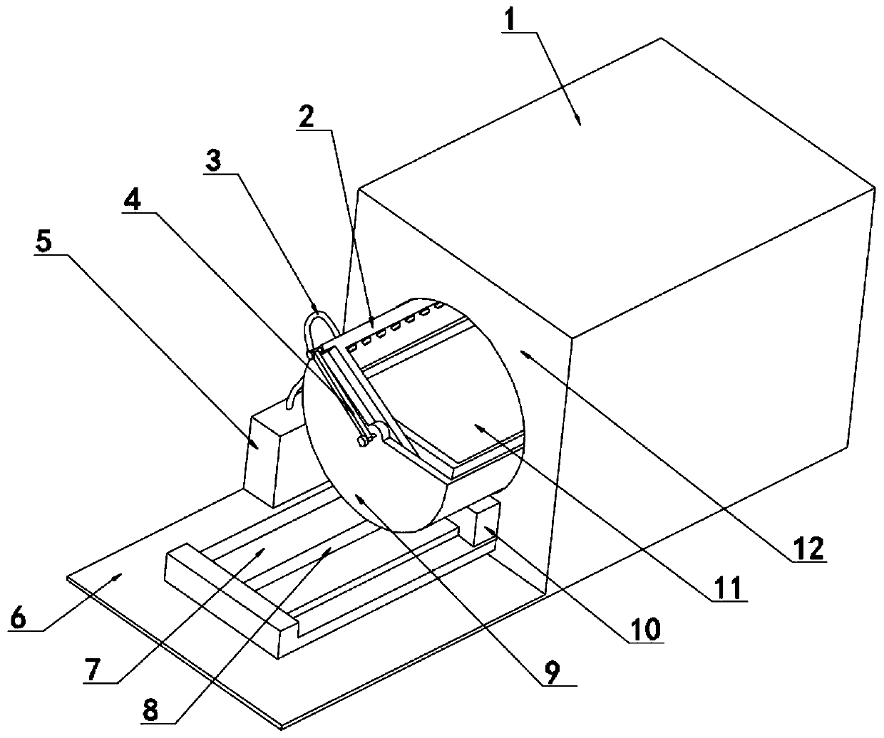
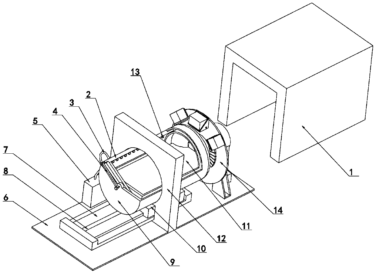
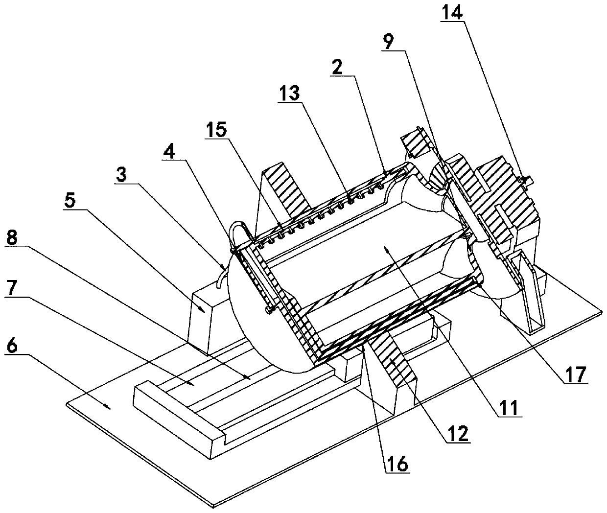
[0031] Embodiment one, with reference to Figure 1-4 , medical image imaging equipment, including a base 6; the imaging equipment 14 arranged on the top side of the base 6 also includes: a cylindrical cavity 9, which can be horizontally movable on the base 6, and the cylindrical cavity 9 has a capacity for accommodating Cavity; support platform 11, and support platform 11 is fixedly installed in the accommodation chamber in a horizontal state, and is used to support the patient to be detected; Ring cover 18, ring cover 18 is movably installed in the accommodation cavity, makes support platform by rotating ring cover 18 11 is isolated from the outside world; protective cover 1, a partition 12 is arranged on one side of the protective cover 1, and the two are used to form an isolation state between the cylindrical cavity 9 and the outside world; the sliding assembly, the sliding assembly is arranged on the base 6, so that the cylindrical cavity 9 can move horizontally under the ...
Embodiment 2
[0033] Embodiment two, refer to figure 2 , the sliding assembly includes: a slide rail 7, the slide rail 7 is fixedly installed on the base 6; a slide block 10, the slide block 10 is slidably connected with the slide rail 7, and the top of the slide block 10 is fixed to the bottom of the cylindrical cavity 9; the slide rail 7 is The convex platform structure extending upward in the middle, the slider 10 is an indented concave platform structure, and cooperates with the slide rail 7 to form a sliding assembly. The vertical sides of the partition 12 are provided with circular grooves 16, and the circular grooves 16 and the cylindrical cavity have 9 arcs. The outer wall of the surface is slidingly connected. Preferably, the slider 10 is clearance-fitted with the partition 12 to increase the protective isolation effect of the partition 12 on the imaging device 14 inside the protective housing 1 and reduce the possibility of dust accumulation at the imaging device 14.
Embodiment 3
[0034] Embodiment three, refer to image 3 , the inner wall of the cylindrical cavity 9 is provided with an annular inner groove 17 along the circumferential direction, the annular cover 18 is slidably connected with the annular inner groove 17, and the left and right ends of the annular cover 18 are rotationally connected with the inner wall of the circular end face of the cylindrical cavity 9 through a rotating shaft, and the supporting platform 11 The first end surface is seamlessly connected with the inner wall of the arc surface of the cylindrical cavity 9, and there is a gap between the second end surface and the inner wall of the arc surface of the cylindrical cavity 9, which is larger than the thickness of the annular cover 18. The cut surface of the annular cover 18 is a 180 ° ring structure, and a rubber pad 2 is installed on the first side end surface. Preferably, the end of the pallet 11 away from the rubber pad 2 is sealed, so that the rubber pad 2 and the pallet 1...
PUM
 Abstract
Description
Claims
Application Information
 - R&D
- Intellectual Property
- Life Sciences
- Materials
- Tech Scout
- Unparalleled Data Quality
- Higher Quality Content
- 60% Fewer Hallucinations
Browse by: Latest US Patents, China's latest patents, Technical Efficacy Thesaurus, Application Domain, Technology Topic, Popular Technical Reports.
© 2025 PatSnap. All rights reserved.Legal|Privacy policy|Modern Slavery Act Transparency Statement|Sitemap|About US| Contact US: help@patsnap.com


