
Electric terminal equipment and working method thereof

A working method and technology of end equipment, applied in electrical components, discontinuous tuning with a separate pre-tuning circuit, transmission system, etc., can solve problems such as unfavorable photoelectric detectors, large 3G network loss, etc., to ensure timely and smooth. , the effect of reducing the frequency of unsmooth

Active Publication Date: 2020-06-12
ARMY ENG UNIV OF PLA
View PDF5 Cites 0 Cited by
  • Summary
  • Abstract
  • Description
  • Claims
  • Application Information

AI Technical Summary

Problems solved by technology

[0008] In order to solve the above-mentioned problems, the present invention provides an electric terminal device and its working method, which effectively avoids the problem that the restoration of the 3G network in the prior art usually consumes more time, which is very unfavorable for the transmission of the electric signal output by the photodetector. deficiencies in timeliness

Method used


Image

  • Electric terminal equipment and working method thereof
  • Electric terminal equipment and working method thereof

Examples


Embodiment Construction

[0060] The present invention will be further described below in conjunction with the accompanying drawings and embodiments.

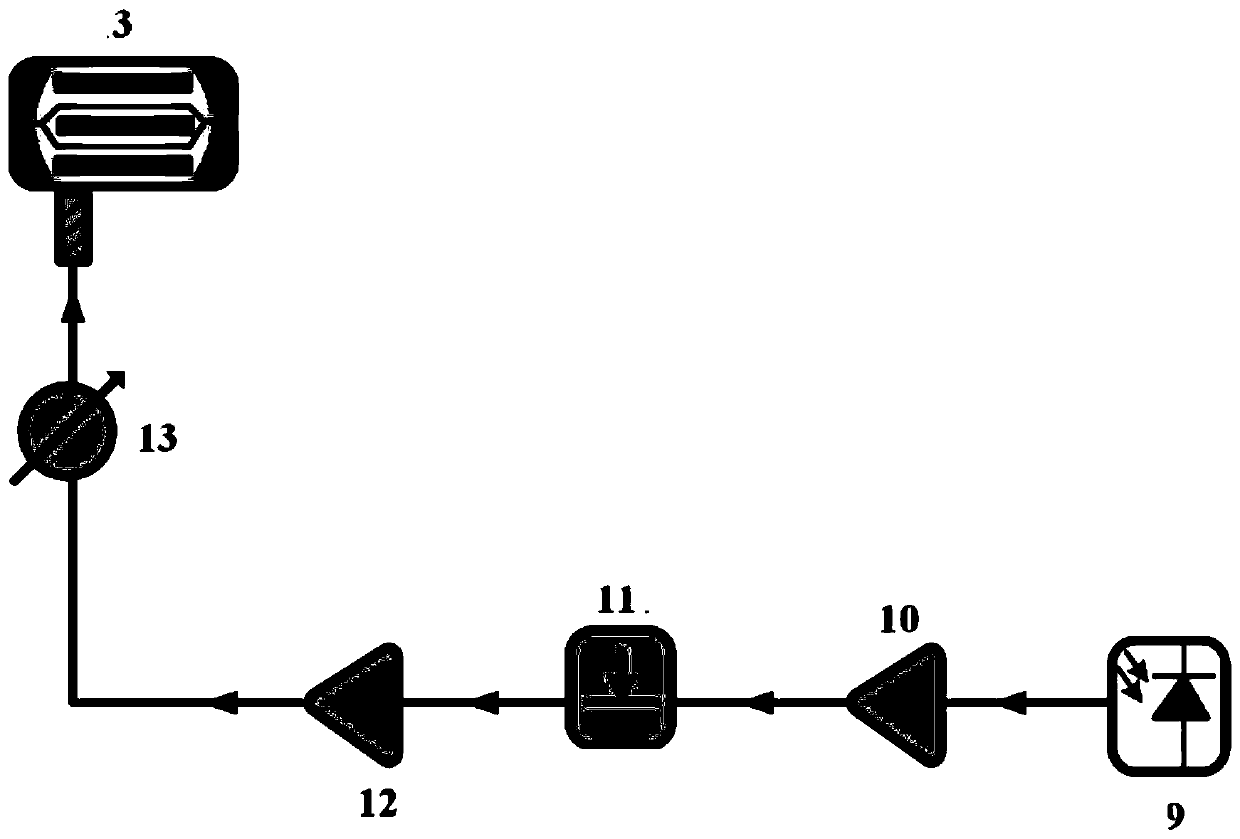
[0061] Such as Figure 1-Figure 2 As shown, the working method of the electric terminal equipment includes:

[0062] The radio frequency signal output by the photodetector 9 is amplified by the first radio frequency amplifier 10 and the second radio frequency amplifier 12 and fed back into the Mach-Zehnder electro-optical intensity modulator 3 to complete the generation of frequency tunable microwave signals;

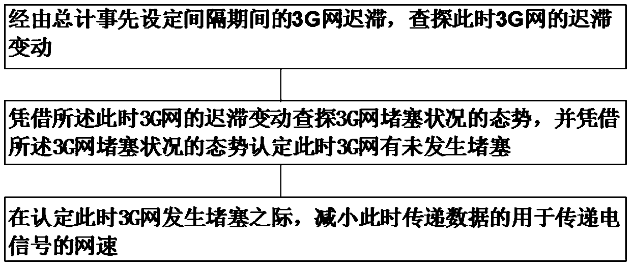
[0063] The electrical signal output by the photoelectric detector is transmitted to the PLC programmable controller, and the PLC programmable controller transmits the electrical signal to the cloud server in the 3G network through the 3G module for display, so as to achieve the purpose of remote monitoring.

[0064] The method in which the PLC programmable controller transmits the electrical signal to the cloud server in the 3G network via the 3...


PUM


Abstract

According to the electric terminal equipment and the working method thereof, a radio frequency signal output by a photoelectric detector is amplified by a first radio frequency amplifier and a secondradio frequency amplifier and then is fed back and input into a Mach-Zehnder electro-optic intensity modulator, and generation of a frequency tunable microwave signal is completed; electric signals output by the photoelectric detector are transmitted to the PLC, and then the PLC transmits the electric signals to a cloud server in a 3G network through the 3G module to be displayed. And the delay change of the 3G network at the moment is detected through the 3G network delay in the preset interval period. And in combination with other structures or methods, the defects that in the prior art, thereduction of the 3G network often consumes longer time, and the timeliness of the transmission of the electric signal output by the photoelectric detector is not facilitated are effectively avoided.

Description

technical field [0001] The invention relates to the technical field of electric terminal equipment, in particular to an electric terminal equipment and a working method thereof. Background technique [0002] In the process of realizing radio frequency tuning by microwave photonics method, electrical terminal equipment is often used, and the electrical terminal equipment includes a first radio frequency amplifier, a radio frequency power divider, a second radio frequency amplifier and a low noise amplifier electrically connected in sequence. The low noise amplifier is connected to the radio frequency input port of the Mach-Zehnder electro-optic intensity modulator of the optical terminal equipment, and the output terminal of the photodetector of the optical terminal equipment is connected to the input terminal of the first radio frequency amplifier. [0003] In this way, the photodetector generates a radio frequency signal; the output radio frequency signal is amplified by th...

Claims


Application Information

Patent Timeline
Patent Type & Authority Applications(China)
IPC IPC(8): H04L29/08H04B10/70H03J5/24
CPCH04L67/10H04L67/125H04B10/70H03J5/24
Inventor 张品傅振华滕义超倪家正
Owner ARMY ENG UNIV OF PLA
Learn More