
Anti-deformation polishing machining device based on thin-walled steel pipe

A thin-walled steel pipe and processing device technology, applied in the field of steel pipe processing, can solve the problems of trouble, affect the connection and fixation, difficult to ensure stability and reliability, and achieve the effect of strong transmission and improved processing applicability

Inactive Publication Date: 2020-06-12
浦江县旭星机械科技有限公司
View PDF0 Cites 0 Cited by
  • Summary
  • Abstract
  • Description
  • Claims
  • Application Information

AI Technical Summary

Problems solved by technology

[0002] Steel pipes, as a pipeline product, are widely used in water bodies or gas transportation devices. Generally, when steel pipes are installed, multiple steel pipes need to be fixedly connected together to form a conveying channel. Generally, welding is used for fixed connection, but , if the outer surface of the steel pipe is very rough and not smooth, it is easy to cause cracking or collapse after connection. Therefore, the outer surface of the steel pipe must be polished before connection;
[0003] With the continuous development of science and technology, the wall thickness of the steel pipe can be made very thin, but this brings certain difficulties to polishing. Due to the thin wall thickness, it is very easy to cause deformation of the thin-walled steel pipe during the polishing process, thereby affecting To the subsequent connection and fixation, generally in actual operation, the workers will add a support on the inner wall of the steel pipe and then polish it. This method is very troublesome, and it is difficult to ensure stability and reliability, and problems are prone to occur

Method used


Image

  • Anti-deformation polishing machining device based on thin-walled steel pipe
  • Anti-deformation polishing machining device based on thin-walled steel pipe
  • Anti-deformation polishing machining device based on thin-walled steel pipe

Examples


Embodiment Construction

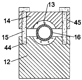
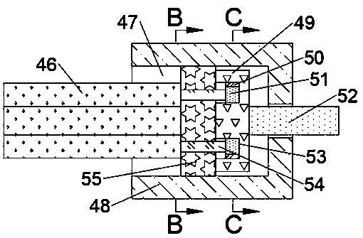
[0017] Combine below Figure 1-5 The present invention is described in detail, and for convenience of description, the orientations mentioned below are now stipulated as follows: figure 1 The up, down, left, right, front and back directions of the projection relationship itself are the same.

[0018] refer to Figure 1-5 According to an embodiment of the present invention, an anti-deformation polishing processing device based on a thin-walled steel pipe includes a base 11 and a body 56, the body 56 is fixed on the top surface of the base 11, and the top of the base 11 A support platform 12 is fixed on the surface, and a thin-walled steel pipe 16 can be placed on the top surface of the support platform 12. The support platform 12 is located on the left side of the body 56, and the body 56 is provided with a lifting cavity with an opening to the left. 22. The lower side of the lifting chamber 22 is connected with a moving chamber 26 that opens to the left. A steel pipe positio...


PUM


Abstract

The invention discloses an anti-deformation polishing machining device based on a thin-walled steel pipe. The anti-deformation polishing machining device comprises a base and a machine body, the machine body is fixedly arranged on the top surface of the base, a supporting platform is fixedly arranged on the top surface of the base, the thin-walled steel pipe can be placed on the top surface of thesupporting platform, the supporting platform is located on the left side of the machine body, a lifting cavity with a leftward opening is formed in the machine body, and a moving cavity with a leftward opening is formed in the lower side of the lifting cavity in a communicating mode. According to the anti-deformation polishing machining device, a method of manual positioning is adopted to make amachining part in the device always at the same level with the steel pipe, the machining applicability of the steel pipes with different diameters is effectively improved, a method of rotating an arc-shaped supporting plate outward to expand and cling to the inner wall of the steel pipe is adopted, and the deformation of the thin-walled steel pipe caused by the excessive polishing pressure when the thin-walled steel pipe is polished on the outer side can be effectively avoided.

Description

technical field [0001] The invention relates to the technical field of steel pipe processing, in particular to an anti-deformation polishing processing device based on thin-walled steel pipes. Background technique [0002] Steel pipes, as a pipeline product, are widely used in water bodies or gas transportation devices. Generally, when steel pipes are installed, multiple steel pipes need to be fixedly connected together to form a conveying channel. Generally, welding is used for fixed connection, but , if the outer surface of the steel pipe is very rough and not smooth, it is easy to cause cracking or collapse after connection. Therefore, the outer surface of the steel pipe must be polished before connection; [0003] With the continuous development of science and technology, the wall thickness of the steel pipe can be made very thin, but this brings certain difficulties to polishing. Due to the thin wall thickness, it is very easy to cause deformation of the thin-walled ste...

Claims


Application Information

Patent Timeline
IPC IPC(8): B24B29/08B24B41/02B24B41/06
CPCB24B29/08B24B41/02B24B41/067
Inventor 沈灵彬
Owner 浦江县旭星机械科技有限公司
Learn More