
Butterfly plate combination device of butterfly valve assembling machine

A combined device and butterfly valve technology, applied in metal processing, metal processing equipment, manufacturing tools, etc., can solve the problems of reducing production efficiency, increasing manufacturing costs and storage management costs, improving processing applicability and reducing production costs. and storage management costs, the effect of ensuring processing quality

Active Publication Date: 2021-03-09
深圳市汇鑫通源科技有限公司
View PDF13 Cites 0 Cited by
  • Summary
  • Abstract
  • Description
  • Claims
  • Application Information

AI Technical Summary

Problems solved by technology

[0003] During the production and processing of butterfly valves, a butterfly valve assembly machine is needed to install the butterfly plate into the valve body. The existing butterfly valve assembly machines use a hydraulic telescopic rod to drive the pressure head down to complete the assembly of the butterfly plate. However, according to the different types of butterfly valves, the sides of the butterfly plate are not all flat, so different pressure heads will be selected according to the shape of the side of the butterfly plate, so that the pressure head can be even on the uneven surface of the butterfly plate. The lower pressure is applied to ensure the combined quality of the butterfly plate and the valve body, but for some butterfly valves produced in small batches, the pressure head needs to be replaced frequently, which reduces the overall production efficiency, and more types of pressure heads are equipped. Also increases manufacturing costs and storage management costs

Method used


Image

  • Butterfly plate combination device of butterfly valve assembling machine
  • Butterfly plate combination device of butterfly valve assembling machine
  • Butterfly plate combination device of butterfly valve assembling machine

Examples


Embodiment 1

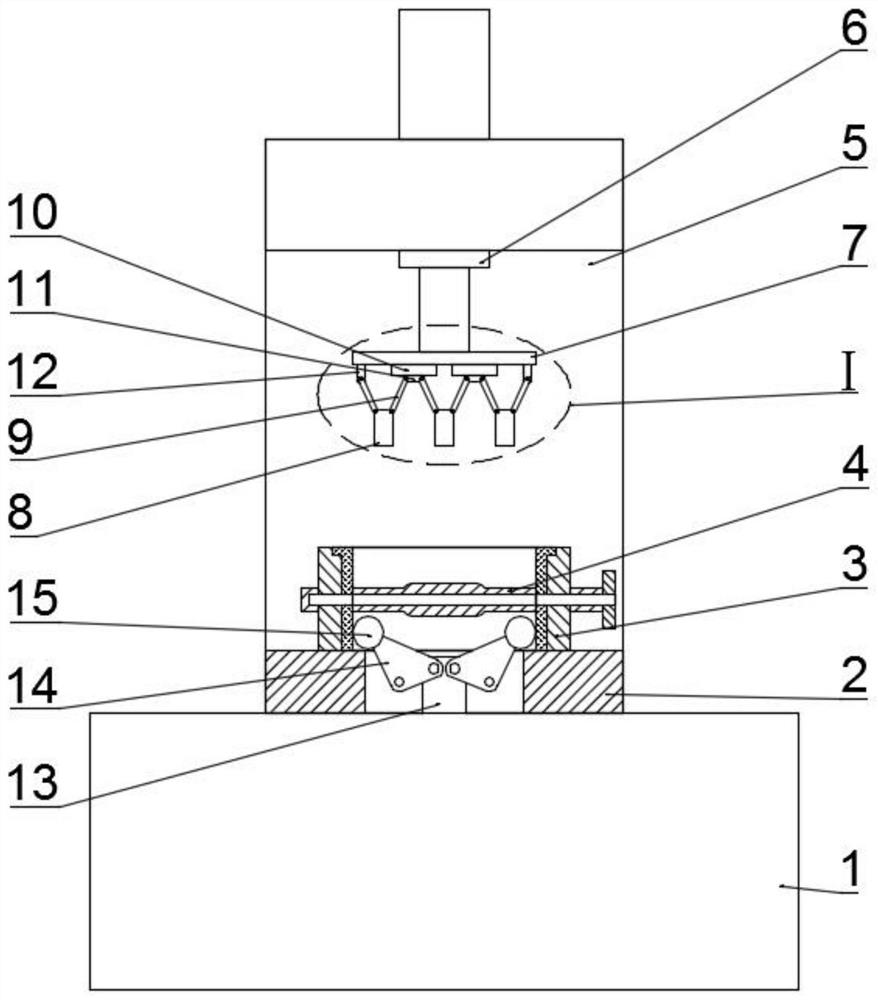
[0028] Such as figure 1 and 2 As shown, a butterfly plate combination device of a butterfly valve assembly machine includes a machine platform 1, a processing platform 2 installed on the machine platform 1 and used for placing the valve body 3, and a vertical plate 5 fixedly arranged on the machine platform 1 The upper part of the processing table 2 is provided with a lifting plate 7, the two ends of the lower surface of the lifting plate 7 are fixedly provided with connecting plates 12, and the middle of the lower surface of the lifting plate 7 is fixedly provided with at least two slide rails 10. The slide rail 10 is provided with a slider 11 that can move along the slide rail 10 with a single degree of freedom, and the connecting plate 12 and the slide rail 10 are located on the same straight line, and a connecting plate 12 is hinged Rod 9, two connecting rods 9 are hinged on the slider 11, a pressing block 8 is arranged below between two adjacent connecting rods 9, and th...

Embodiment 2

[0034] Such as image 3 and 4 As shown, a butterfly plate combination device of a butterfly valve assembly machine includes a machine platform 1, a processing platform 2 installed on the machine platform 1 and used for placing the valve body 3, and a vertical plate 5 fixedly arranged on the machine platform 1 The upper part of the processing table 2 is provided with a lifting plate 7, the two ends of the lower surface of the lifting plate 7 are fixedly provided with connecting plates 12, and the middle of the lower surface of the lifting plate 7 is fixedly provided with at least two slide rails 10. The slide rail 10 is provided with a slider 11 that can move along the slide rail 10 with a single degree of freedom, and the connecting plate 12 and the slide rail 10 are located on the same straight line, and a connecting plate 12 is hinged Rod 9, two connecting rods 9 are hinged on the slider 11, a pressing block 8 is arranged below between two adjacent connecting rods 9, and th...

Embodiment 3

[0040] Such as Figure 5-7 As shown, a butterfly plate combination device of a butterfly valve assembly machine includes a machine platform 1, a processing platform 2 installed on the machine platform 1 and used for placing the valve body 3, and a vertical plate 5 fixedly arranged on the machine platform 1 The upper part of the processing table 2 is provided with a lifting plate 7, the two ends of the lower surface of the lifting plate 7 are fixedly provided with connecting plates 12, and the middle of the lower surface of the lifting plate 7 is fixedly provided with at least two slide rails 10. The slide rail 10 is provided with a slider 11 that can move along the slide rail 10 with a single degree of freedom, and the connecting plate 12 and the slide rail 10 are located on the same straight line, and a connecting plate 12 is hinged Rod 9, two connecting rods 9 are hinged on the slider 11, a pressing block 8 is arranged below between two adjacent connecting rods 9, and the ot...


PUM


Abstract

The invention provides a butterfly plate combination device of a butterfly valve assembling machine, and relates to the technical field of valve production. The butterfly plate combination device of the butterfly valve assembling machine comprises a machine table, a machining table installed on the machine table and used for containing valve bodies and a vertical plate fixedly arranged on the machine table, and a lifting plate is arranged at the upper part of the machining table. According to the butterfly plate combination device, balanced downward pressure can also be applied to non-planar butterfly plates, so that the accuracy of combined installation of the different types of butterfly plates and the valve bodies is guaranteed, for different types of butterfly valves, a pressure head does not need to be replaced frequently, the production efficiency is guaranteed, and the production cost and the storage and management cost are also reduced; according to the butterfly plate combination device, the butterfly plates of the different types of butterfly valves can be pressed down to proper positions, and therefore the machining applicability of the butterfly plate combination deviceis improved; and by arranging a valve body limiting mechanism, the valve bodies to be machined can be quickly and firmly limited by the butterfly plate combination device, and the machining quality is guaranteed.

Description

technical field [0001] The invention relates to the technical field of valve production, in particular to a butterfly plate assembly device of a butterfly valve assembly machine. Background technique [0002] Butterfly valve, also known as flap valve, is a regulating valve with simple structure, which can be used for switch control of low-pressure pipeline medium. of a valve. The valve can be used to control the flow of various types of fluids such as air, water, steam, various corrosive media, mud, oil, liquid metal and radioactive media; it mainly plays the role of cutting and throttling on the pipeline; the opening and closing parts of the butterfly valve are A disc-shaped butterfly plate rotates around its own axis in the valve body to achieve the purpose of opening and closing or adjustment. [0003] During the production and processing of butterfly valves, a butterfly valve assembly machine is needed to install the butterfly plate into the valve body. The existing bu...

Claims


Application Information

Patent Timeline
Patent Type & Authority Applications(China)
IPC IPC(8): B23P19/027
CPCB23P19/027
Inventor 不公告发明人
Owner 深圳市汇鑫通源科技有限公司
Learn More