Low-cost high-power-density single-phase high-speed hybrid excitation permanent magnet motor and method

A high power density, permanent magnet motor technology, applied in synchronous motors with stationary armatures and rotating magnets, AC motor control, electric components, etc. and other problems to achieve the effect of improving performance and power density, reducing manufacturing costs, and avoiding magnetic performance degradation.

Active Publication Date: 2020-06-09
SHANDONG UNIV
View PDF8 Cites 3 Cited by
  • Summary
  • Abstract
  • Description
  • Claims
  • Application Information

AI Technical Summary

Problems solved by technology

[0007] 1. The permanent magnets of most existing permanent magnet motors are located on the rotor and rotate with the rotor during operation. The permanent magnets need to be fixed by special procedures, and the manufacturing cost is high. Especially when the motor speed is high, it is more difficult to fix the permanent magnets. Located on the rotor, it is difficult to dissipate heat during operation, and the temperature rise and vibration caused by the rotation of the rotor will cause damage to the mechanical structure of the permanent magnet and irreversible demagnetization
[0008] 2. Existing permanent magnet motors are generally three-phase, and the power inverter circuit of the motor requires at least 6 power switching devices, such as IGBT or MOSFET, as well as the corresponding driving circuit and protection circuit for driving the power switching devices. The cost of the motor power inverter circuit is quite high, even reaching two to three times the cost of the motor body. The increase in the number of power switching devices increases the complexity of the control circuit, increases the possibility of device failure, and reduces the reliability of the system during operation.
[0009] 3. In addition, the existing permanent magnet motors mostly use distributed windings or concentrated windings spanning multiple pole pitches. Generally, the ends of the windings are long, the amount of copper used is large, the manufacturing cost is high, the copper consumption is large during the operation of the motor, and the efficiency Low disadvantages, especially for motors with large outer diameter and small axial length, that is, a large ratio of diameter to length, this disadvantage is particularly prominent, and special winding coil connection methods are required to reduce the winding end and reduce the Use less copper to improve the efficiency of motor operation
[0010] 4. Permanent magnets with high magnetic energy product are generally required on the rotor, such as NdFeB. The practical engineering application of permanent magnet motor
[0011] 5. In a considerable part of high-speed fan and pump drive loads, the drive motor is required to be able to perform smooth speed regulation within a wide speed range, to achieve constant power operation in a wide speed range, and to have high operating efficiency. Permanent magnet motors After the permanent magnet is manufactured, the magnetic flux remains unchanged, and the back electromotive force of the motor is determined. Under the condition of a certain inverter capacity, the increase of the motor speed is limited. Application of fan and pump load occasions
However, the significant disadvantages of electrically excited switched reluctance motors are their large copper consumption and low efficiency.

Method used


Image

  • Low-cost high-power-density single-phase high-speed hybrid excitation permanent magnet motor and method
  • Low-cost high-power-density single-phase high-speed hybrid excitation permanent magnet motor and method
  • Low-cost high-power-density single-phase high-speed hybrid excitation permanent magnet motor and method

Examples


Embodiment 1

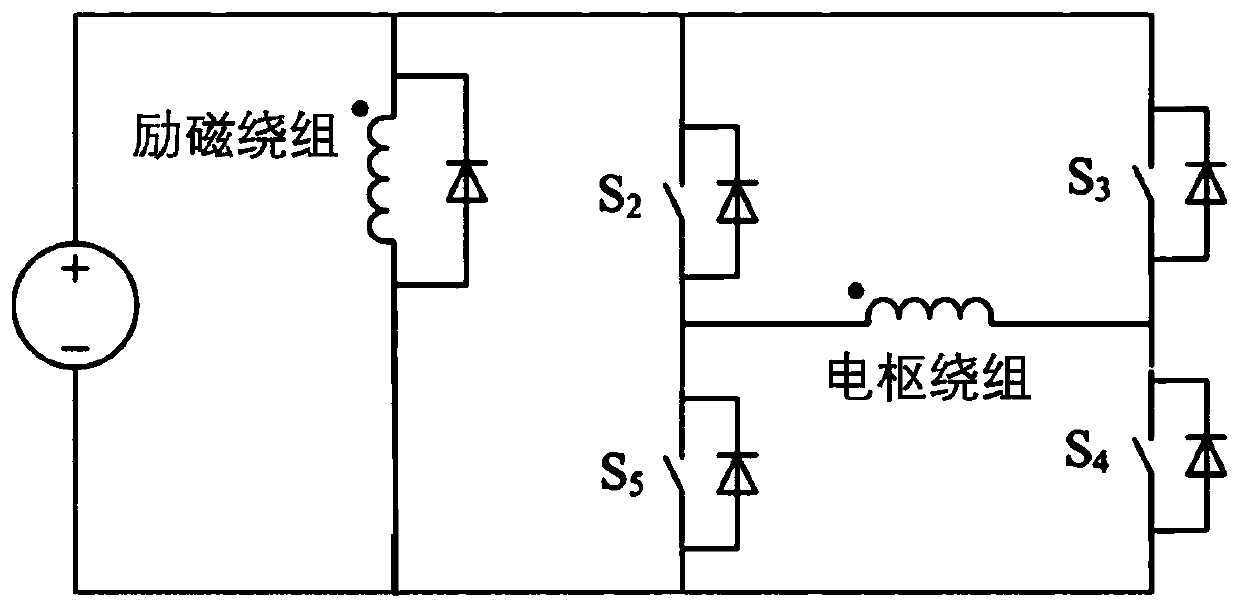
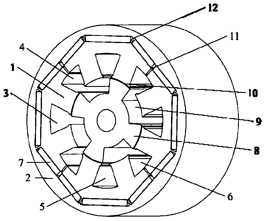
[0067] This embodiment discloses a low-cost, high-power-density single-phase high-speed hybrid excitation permanent magnet motor, including a stator and a rotor, and the stator includes stator slots, stator teeth, permanent magnet slots, and a stator yoke. The stator slot is composed of an armature slot and an excitation slot. A permanent magnet slot is arranged above the stator slot. A total of three pieces of ferrite with the same magnetization direction are placed between the additional air gaps. The permanent magnets are placed in the in the permanent magnet slot. The armature slots and excitation slots are alternately arranged at intervals along the circumference, a set of armature windings is placed in the armature slots, and a set of excitation windings is placed in the excitation slots. The magnetic concentration effect is realized by arranging the low-cost ferrite according to a certain angle, and the stator is connected into a whole through a magnetic bridge; the mot...


PUM


Abstract

The invention discloses a low-cost high-power-density single-phase high-speed hybrid excitation permanent magnet motor and method. The motor comprises a stator and a rotor; armature grooves and excitation grooves are alternately arranged at intervals along the circumference; a set of armature windings are disposed in the armature grooves; a set of excitation windings are disposed in the excitationgrooves; the rotor comprises rotor teeth, rotor grooves are formed between the adjacent rotor teeth, and main air gaps are formed between the stator teeth and the rotor teeth; the iron core between the excitation groove where the excitation winding is located and the permanent magnet above the excitation groove is disconnected in the radial direction, additional air gaps are formed, and ferriteswhich are the same in the magnetizing direction and arranged in a short-long-short mode to form a pole are placed between the additional air gaps. Most of magnetic flux passes through the main air gaps by matching the length and the mounting angle of the ferrites under the same polarity, so that a magnetism gathering function is realized, and the performance and the power density of the motor areimproved.

Description

technical field [0001] The invention belongs to the technical field of motors, and in particular relates to a low-cost, high-power-density, single-phase, high-speed hybrid excitation permanent magnet motor and its method. Background technique [0002] The statements in this section merely provide background information related to the present disclosure and do not necessarily constitute prior art. [0003] High-speed fans, pumps and other devices are widely used in various fields of the national economy, and a considerable number of fan and pump loads need speed regulation, so high-speed fans and pump drive motors are widely used in this field. Different driving conditions of fans and pumps have different requirements on the performance of the driving motor. The traditional method is to adjust the flow rate through a throttling device, which is relatively simple, but will cause a large waste of energy. At the same time, due to the existence of deficiencies such as the immatu...

Claims


Application Information

Patent Timeline
Patent Type & Authority Applications(China)
IPC IPC(8): H02K1/16H02K1/17H02K1/24H02K3/16H02K3/28H02K21/14H02K21/02H02K21/04H02K1/02H02P27/06
CPCH02K1/02H02K1/165H02K1/17H02K1/24H02K3/16H02K3/28H02K21/024H02K21/04H02K21/14H02K2201/03H02K2213/03H02P27/06
Inventor 王道涵臧鹏
Owner SHANDONG UNIV
Why Eureka
Try Eureka