Movable rapid self-heating hydrogen production device and application thereof

A mobile device and hydrogen technology, applied in hydrogen, hydrogen production, inorganic chemistry, etc., can solve the problems of high hydrogen storage density, difficult liquefaction, and poor overall safety, and achieve high hydrogen concentration, fast response, and good Effect of Low Temperature Ammonia Decomposition Performance

Active Publication Date: 2020-06-09
DALIAN INST OF CHEM PHYSICS CHINESE ACAD OF SCI
View PDF6 Cites 3 Cited by
  • Summary
  • Abstract
  • Description
  • Claims
  • Application Information

AI Technical Summary

Problems solved by technology

However, it is well known that hydrogen molecules are extremely small, have strong permeability, are easy to leak, and are difficult to liquefy. The storage and transportation of hydrogen are difficult problems in the world, which limits the application of large-scale production of hydrogen away from manufacturing sites
As far as the inventor knows, there are three commonly used methods for decentralized on-site hydrogen storage and hydrogen supply: the first method is to use high-pressure hydrogen storage tanks. Multi-stage decompression to the required pressure and output for use. This method of hydrogen supply is inefficient, consumes a lot of energy when compressed into cans, and there is a risk of leakage in high-pressure storage. The decompression system is complicated and the overall safety is not good; the second method is to use Low-temperature liquid hydrogen has a high hydrogen storage density. The problem is that it needs to be stored at ultra-low temperature (-253°C). The storage tank requires high insulation, and the leakage loss of liquid hydrogen is large, which has potential safety hazards. The third method is to use hydrogen storage materials to store hydrogen. The hydrogen storage density Low (available hydrogen storage is less than 2%), and it needs to be heated to release it well, which limits its application range
The hydrogen supply method that has been studied more now is to produce hydrogen on-site through steam reforming of liquid fuels such as gasoline and methanol. First, high-temperature steam reforming of gasoline and methanol into CO and H 2 , then CO is further combined with H 2 Convert O to CO 2 and H 2 , the residual CO is eliminated through partial oxidation conversion. This method of hydrogen supply uses liquid fuel, which solves the problem of fuel transportation, and the fuel can be stored under normal pressure, avoiding the safety hazard of direct use of hydrogen, and the energy consumption is also low, but At the same time, it also brings some new problems to be solved urgently: 1. The hydrogen supply device starts to reach the reaction equilibrium, and it takes a long time to realize the stable output of hydrogen, that is, a long start-up time is required; 2. There are multiple reaction processes, and the reaction system is not suitable for reaction Temperature, pressure and other conditions are sensitive, and complex reactors and operation control systems need to be designed to realize the output of hydrogen products that meet the requirements of use, which is not suitable for occasions that require intermittent use of hydrogen; 3. The reforming package reaction is an endothermic process, so It needs an external heat source or catalytic combustion to consume part of the fuel to heat the reactor to maintain the reaction, which requires the consumption of external energy or a complex self-heating reactor; 4. The use of gasoline, methanol and other hydrocarbon fuels to reform hydrogen will inevitably produce CO , CO can poison the electrocatalyst, resulting in reduced fuel cell performance

Method used


Image

  • Movable rapid self-heating hydrogen production device and application thereof
  • Movable rapid self-heating hydrogen production device and application thereof
  • Movable rapid self-heating hydrogen production device and application thereof

Examples


Embodiment

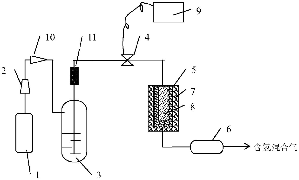
[0024] The invention uses hydrazine or hydrazine hydrate as a fuel, and provides a mobile on-site hydrogen production device that rapidly and autothermally decomposes the fuel to generate hydrogen. It includes a pressure cylinder 1, a pressure regulating valve 2, a hydrazine fuel storage tank 3, a catalytic reactor 5, and a purifier 6; the hydrazine fuel storage tank 3 and the catalytic reactor 5 are connected to each other through pipelines, and the outlet gas of the catalytic reactor 5 passes The purifier 6 is output from the external pipeline; the hydrazine fuel storage tank 3 is connected to the pressure gas cylinder 1 through a pipeline, and a pressure regulating valve 2 is provided on the connecting pipeline; the catalytic reactor 5 is covered with a quartz wool insulation layer 7, The catalytic reactor is filled with a high-efficiency catalyst bed 8;

[0025] On the connecting pipeline of hydrazine fuel storage tank 3 and catalytic reactor 5, be provided with filter 11 ...


PUM


Abstract

The invention discloses a movable on-site hydrogen production device for rapidly and self-thermally decomposing anhydrous hydrazine fuel into nitrogen-hydrogen mixed gas. The movable on-site hydrogenproduction device is suitable for providing a hydrogen source for a fuel cell or being used as a hydrogen source in field operation and metal processing. The device comprises a pressure gas cylinder,a pressure regulating valve, a fuel storage tank, an electromagnetic valve, a catalytic reactor, a catalyst bed layer, a quartz cotton fiber heat preservation layer, a hydrogen purification tank, a connecting pipeline and the like. According to the invention, the device can quickly and efficiently decompose anhydrous hydrazine fuel to generate hydrogen, the hydrogen is output within the second-level starting time of the device, the designed flow is stably output within 4-5 minutes, an external heat source is not needed, the system is simple and reliable, the concentration of hydrogen in the product is about 65%, the rest is nitrogen without battery catalyst poisons such as carbon monoxide and the like, the flow of the generated hydrogen can be conveniently adjusted between 29.4 L/min and 94.8 L/min (the standard state is 25 DEG C, 1atm), and the requirement for supplying hydrogen to a 1-5 kilowatt fuel cell and other hydrogen requirements for field operation are met.

Description

technical field [0001] The invention relates to a mobile on-site hydrogen production device, in particular to a mobile on-site hydrogen production device which rapidly and autothermally decomposes anhydrous hydrazine fuel into nitrogen and hydrogen mixture gas, and is suitable for providing hydrogen sources for fuel cells Or as a hydrogen source in emergency situations, field operations, and metal processing. Background technique [0002] Hydrogen is an efficient and clean energy, widely used in the chemical industry, metal processing and field operations, etc. The development and maturity of fuel cell technology has made it possible for ordinary people to use hydrogen on a large scale. However, it is well known that hydrogen molecules are extremely small, have strong permeability, are easy to leak, and are difficult to liquefy. The storage and transportation of hydrogen is a difficult problem in the world, which limits the application of large-scale production of hydrogen f...

Claims


Application Information

Patent Timeline
Patent Type & Authority Applications(China)
IPC IPC(8): C01B3/04
CPCC01B3/047C01B3/04Y02E60/36
Inventor 赵许群
Owner DALIAN INST OF CHEM PHYSICS CHINESE ACAD OF SCI
Why Eureka
Try Eureka