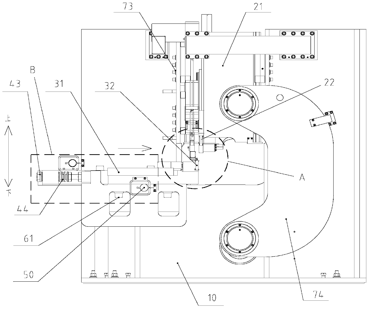
Cutting device for wire cord fabric

A technology of steel cord and cutting knife, which is applied in tires, metal processing, and other household appliances, etc., and can solve the problems of inaccurate dial indicator clearance and blind adjustment of screw rods, etc.

Pending Publication Date: 2020-06-09
MESNAC +1
View PDF0 Cites 0 Cited by
  • Summary
  • Abstract
  • Description
  • Claims
  • Application Information

AI Technical Summary

Problems solved by technology

[0006] The main purpose of the present invention is to provide a steel cord cutting device to solve the problem of blindly adjusting the screw due to the inaccurate gap displayed by the dial indicator in the related art

Method used


Image

  • Cutting device for wire cord fabric
  • Cutting device for wire cord fabric
  • Cutting device for wire cord fabric

Examples


Embodiment Construction

[0027] The following will clearly and completely describe the technical solutions in the embodiments of the present invention with reference to the accompanying drawings in the embodiments of the present invention. Obviously, the described embodiments are only some, not all, embodiments of the present invention. The following description of at least one exemplary embodiment is merely illustrative in nature and in no way taken as limiting the invention, its application or uses. Based on the embodiments of the present invention, all other embodiments obtained by persons of ordinary skill in the art without creative efforts fall within the protection scope of the present invention.

[0028] It should be noted that the terminology used here is only for describing specific implementations, and is not intended to limit the exemplary implementations according to the present application. As used herein, unless the context clearly dictates otherwise, the singular is intended to include...


PUM


Abstract

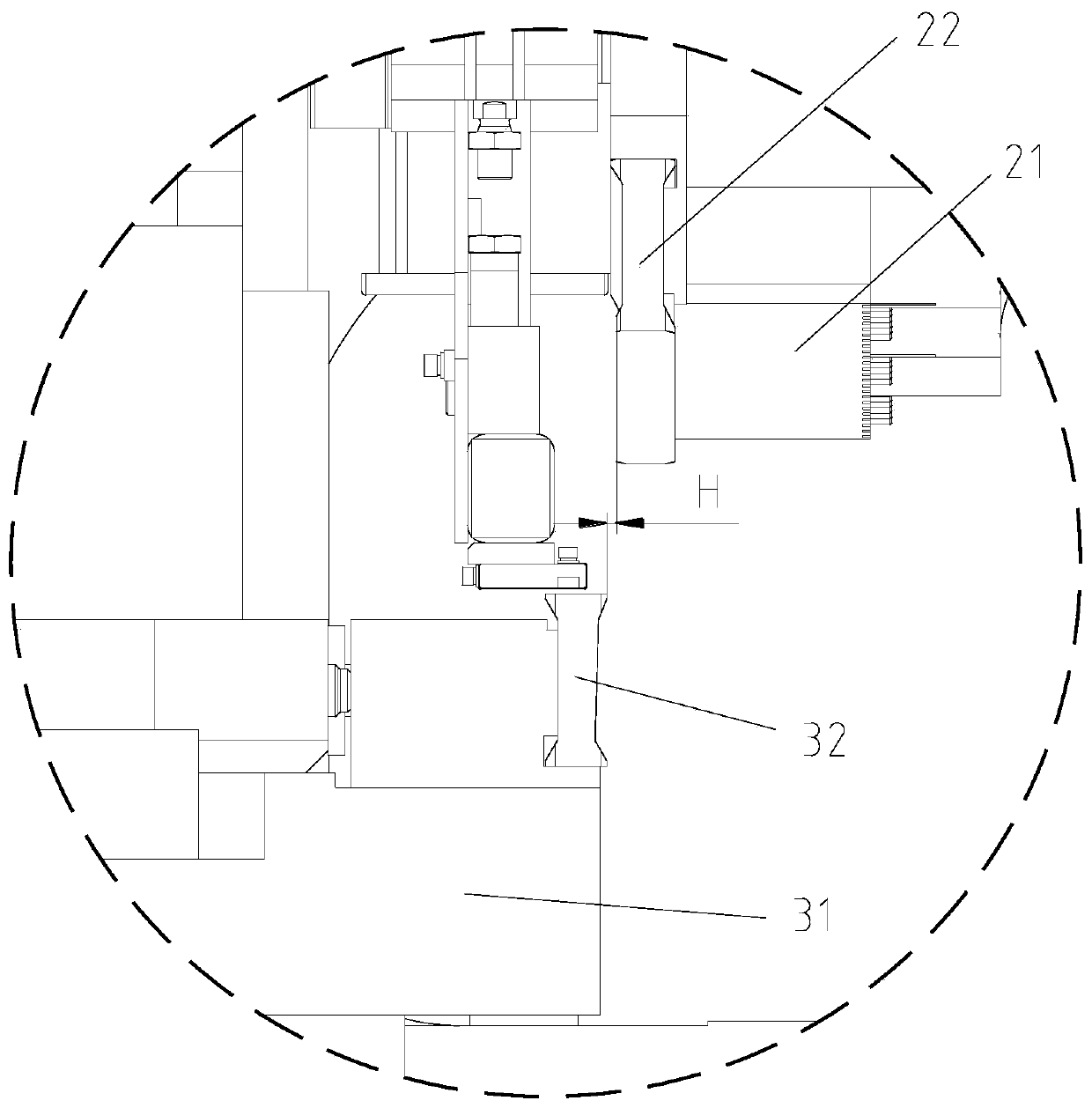
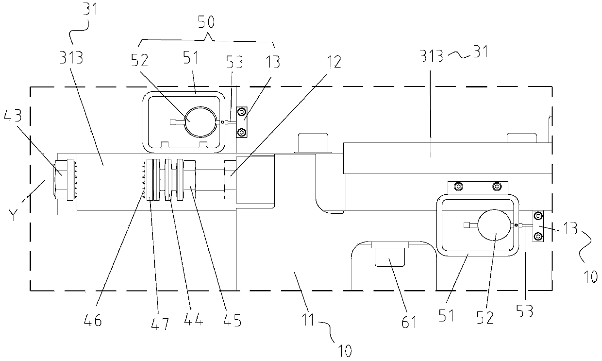
The invention provides a cutting device for wire cord fabric. The device comprises a rack, an upper cutter mechanism, a lower cutter mechanism, adjusting mechanisms and display instrument assemblies;the lower cutter mechanism is arranged in the moving direction of a cutter board, and a cutter gap H is formed between an upper cutter and a lower cutter; the adjusting mechanisms are arranged on thecutter board and connected with the rack, and the adjusting mechanisms comprises first mounting holes, screw holes, screw rods, elastic pieces and first nuts, wherein the first mounting holes, the screw holes, the screw rods, the elastic pieces and the first nuts are coaxially arranged, the first mounting holes are formed in the cutter board, the screw holes are formed in the rack, an adjusting gap is formed between the cutter board and the rack, the screw rods penetrate through the first mounting holes and the screw holes, the first nuts extrude the elastic pieces so as to enable the elasticpieces to apply elastic force to the cutter board, and the screw rods are screwed to drive the cutter board to move to adjust the size of the adjusting gap so as to adjust the size of the cutter gap H; and the display instrument assemblies are arranged on the cutter board and abut against the rack. According to the technical scheme, the problem that in the related art, the gap amount displayed bya dial indicator is inaccurate, so that the screw rods are blindly adjusted is effectively solved.

Description

technical field [0001] The invention relates to radial tire production equipment, in particular to a cutting device for steel cords. Background technique [0002] The carcass cord or belt layer cord of the radial tire of the related art needs to be rewound into a cord roll for use by a tire building machine after being cut, jointed, and wrapped in a cutting production line. The cutting device of the cutting production line is responsible for cutting the cord into fixed-length cord strips, and the conveyor belt receives the cut cord strips and sends them to the subsequent splicing device of the production line. In the related art, the cord strips are delivered and fixed in length by a four-bar mechanism and a magnetic beam arranged at the fabric delivery end, cut by upper and lower knives, and a conveyor belt is used to receive the cut cord strips. [0003] However, in the C-shaped cutting device of the cutting production line, it is difficult to adjust the gap between the c...

Claims


Application Information

Patent Timeline
Patent Type & Authority Applications(China)
IPC IPC(8): B29D30/46B26D7/26
CPCB29D30/46B26D7/2628
Inventor 李奇张丰仙张昌帅
Owner MESNAC
Why Eureka
Try Eureka