
Automatic beating device for scraper production

An automatic, rotating shaft technology, applied in the direction of impact tools, light impact tools, cleaning methods using gas flow, etc., can solve the problems of constantly moving scrapers, low work efficiency, and safety risks, so as to improve work efficiency and equipment Ease of use and clean equipment

Pending Publication Date: 2020-06-09
孙忠君
View PDF5 Cites 6 Cited by
  • Summary
  • Abstract
  • Description
  • Claims
  • Application Information

AI Technical Summary

Problems solved by technology

[0005] In order to overcome the shortcomings of the current way of hitting the scraper that requires manual hitting, continuous movement of the scraper, low work efficiency, and safety risks, the technical problem is to provide a method that automatically hits the scraper and automatically moves the scraper. Automatic beating device for scraper production that improves work efficiency and reduces safety risks

Method used


Image

  • Automatic beating device for scraper production
  • Automatic beating device for scraper production
  • Automatic beating device for scraper production

Examples


Embodiment 1

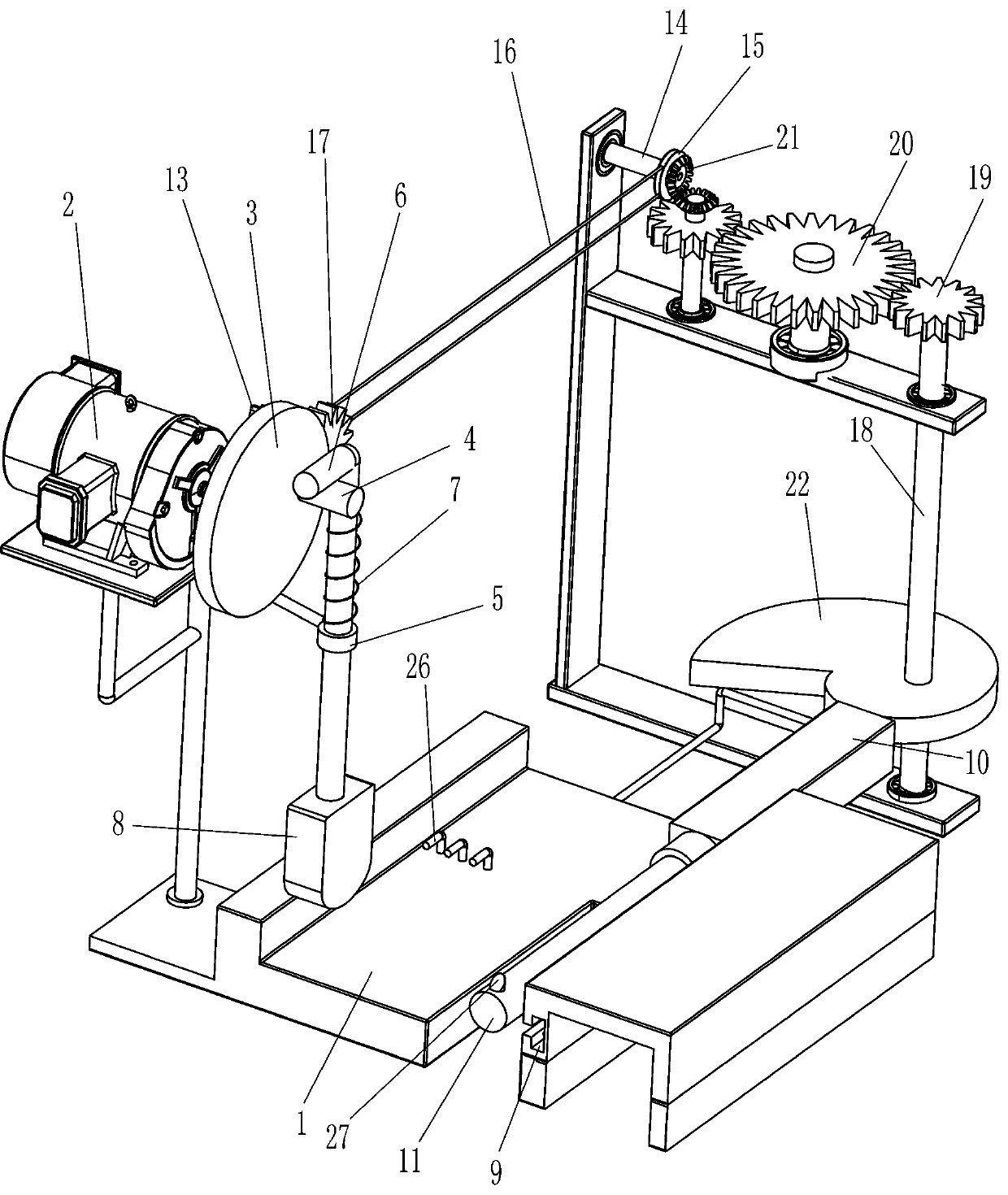
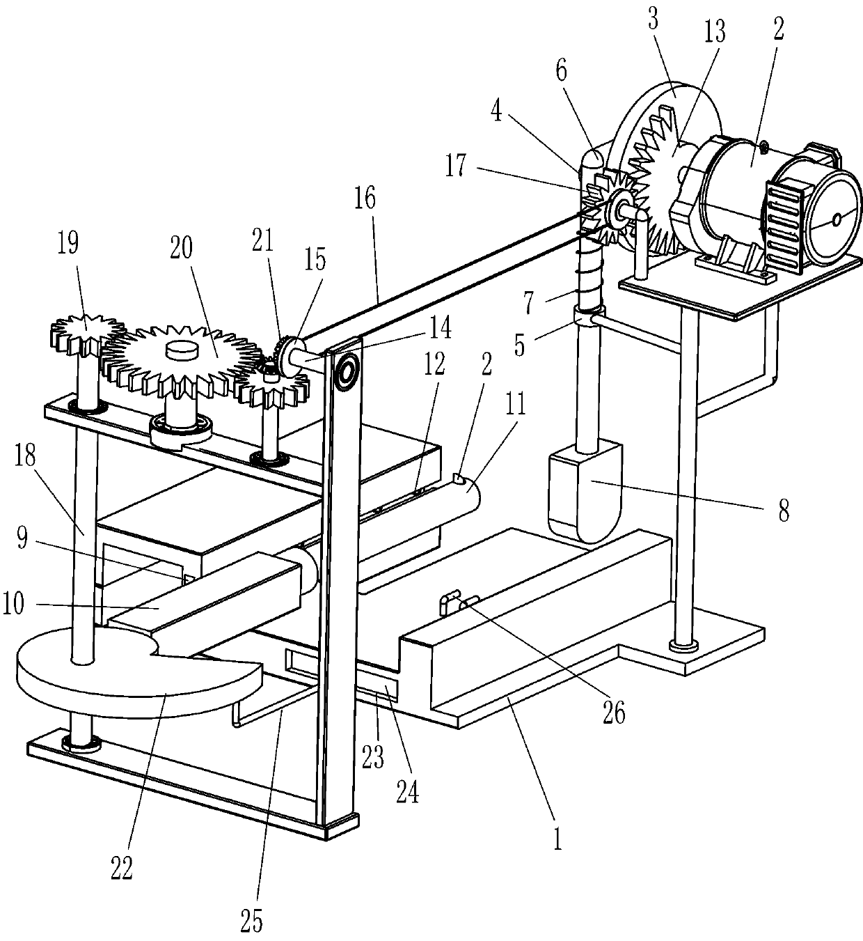
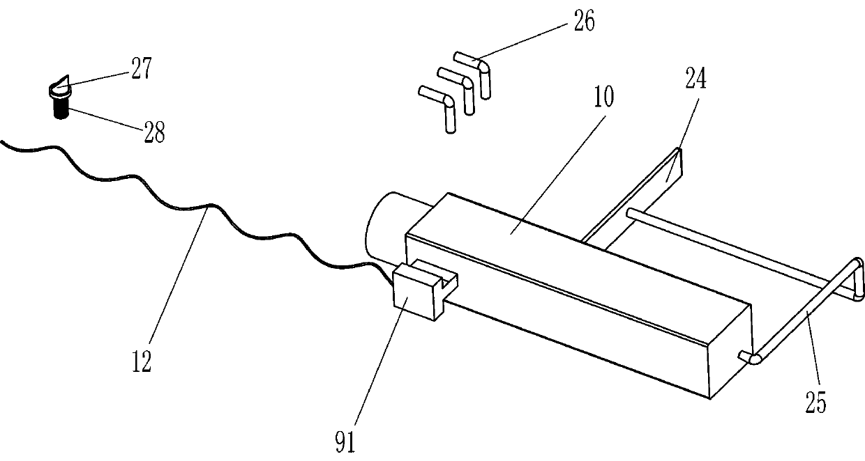
[0019] An automatic beating device for scraper production, such as figure 1 and 2 As shown, it includes a base 1, a hammer assembly and a placement assembly. The base 1 is provided with a hammer assembly powered by a motor, and the base 1 is provided with a placement assembly for placing a scraper.

[0020] Such as figure 1 and 2 As shown, the hammering assembly includes a geared motor 2, a disc 3, a push rod 4, a guide sleeve 5, an L-shaped sliding rod 6, a first spring 7 and a knocking block 8, and a geared motor is provided on the front left side of the top of the base 1 2. A disc 3 is provided on the output shaft of the gear motor 2, a push rod 4 is provided at the eccentric position on the right side of the disc 3, a guide sleeve 5 is provided on the left front side of the base 1, and an L-shaped sliding type is provided inside the guide sleeve 5. Slide bar 6, the first spring 7 is connected between the L-shaped slide bar 6 and the guide sleeve 5, the L-shaped slide ba...

Embodiment 2

[0026] Such as figure 1 and 2 As shown, on the basis of Embodiment 1, in order to use the device better, it also includes a sector gear 13, a first rotating shaft 14, a pulley 15, a flat belt 16, a first gear 17, a second rotating shaft 18, The second gear 19, the third gear 20, the bevel gear 21 and the cam 22, the disc 3 is provided with a sector gear 13, the left part of the rear side of the base 1 is provided with the first rotating shaft 14 through the rotation of the bearing seat, and the front side of the base 1 The left rotary type is provided with a first gear 17, the first gear 17 meshes with the sector gear 13, the first rotating shaft 14 and the first gear 17 are all keyed with a pulley 15, and a flat belt 16 is wound between the pulleys 15, and the base 1. The rear right part of the rotating type is provided with a second rotating shaft 18. Both the top of the second rotating shaft 18 and the rear left part of the base 1 are provided with a second gear 19. The ro...


PUM


Abstract

The invention relates to a beating device, in particular to an automatic beating device for scraper production. The technical aim of the automatic beating device for scraper production is that a scraper is automatically beaten and moved, thus the work efficiency is improved, and the safety risk is reduced. The automatic beating device for scraper production comprises a base, a hammering assembly,a placement assembly and the like; and the hammering assembly powered by a motor is arranged on the base, and the placement assembly for placing the scraper is arranged on the base. Through cooperation of a push rod and an L-shaped sliding rod, the scraper does not need to be manually hammered, and thus the work efficiency is improved; through cooperation of a sliding groove and a sliding block, the scraper can be constantly moved to enable a hammer to hammer different parts of the scraper, and thus the safety risk is reduced; and through cooperation of a sector gear and a first gear, the scraper does not need to be manually moved, and thus the automatic beating device is move convenient to use.

Description

technical field [0001] The invention relates to a beating device, in particular to an automatic beating device for scraper production. Background technique [0002] The scraper is the main tool for scraping. Generally, high carbon tool steel is used to make the scraper. According to the scraping surface of the workpiece, the scrapers can be divided into three categories: flat scrapers, triangular scrapers and crescent-shaped scrapers. When grinding the scraper, it is necessary to hold the scraper and grind it on the grindstone. [0003] At present, the scraper is hit by manually holding a hammer. During the beating process, it is necessary to manually change the hitting position of the scraper. The mobile scraper has low work efficiency and safety risks. [0004] Therefore, it is necessary to develop an automatic beating device for scraper production that automatically beats the scraper, automatically moves the scraper, improves work efficiency, and reduces safety risks. ...

Claims


Application Information

Patent Timeline
IPC IPC(8): B25D11/00B08B5/02
CPCB25D11/00B08B5/02
Inventor 孙忠君
Owner 孙忠君
Learn More