Hard rock roadway excavation mainly relies on the
drilling and blasting method. Newly developed equipment such as rock drilling rigs, backhoe loaders, and rock roadway drilling units have basically solved the main processes of drilling and
gangue extraction. However, the blasting process has always been It is the
bottleneck that restricts the level of single entry, mainly as follows: (1) The
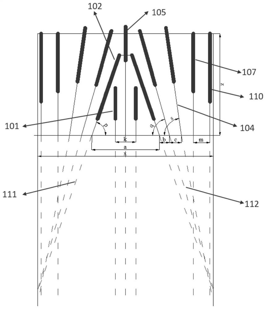
cutting cavity is small, generally the width of the cavity opening is 0.8m ~ 1.2m, and the width of the bottom of the cavity is 0.2 ~ 0.4m. Generally, single wedge,
double wedge, wedge Direct
hybrid cutting method, the actual depth of the cavity after cutting blasting is less than 2.5m (belonging to medium and
deep hole blasting), the actual blasthole utilization is 70% to 80% (drilling 3m, the actual utilization hole depth is 2.2m), resulting in cyclic footage Generally, it is 2-2.5m, and the monthly single entry level is generally 60m-70m; (2) 32mm large-
diameter drug rolls are used, and the
peripheral spacing is controlled at 300mm-400mm, resulting in high
drug density. Serious over- and under-excavation, poor roadway formation, large amount of secondary renovation works around, time-consuming, large amount of
shotcrete, high cost, and unfavorable for surrounding rock stability, low roadway support efficiency, and difficulty in increasing the excavation speed; (3) When the rock is hard, it is generally solved by increasing the number of blastholes and loading more explosives, resulting in a large number of gouges in the whole section, a long time for gouging holes, a large amount of charge, large
blasting vibration, and a long throwing distance. There are many
gangue in the back, and the gangue needs to be crushed twice, which seriously restricts the excavation speed
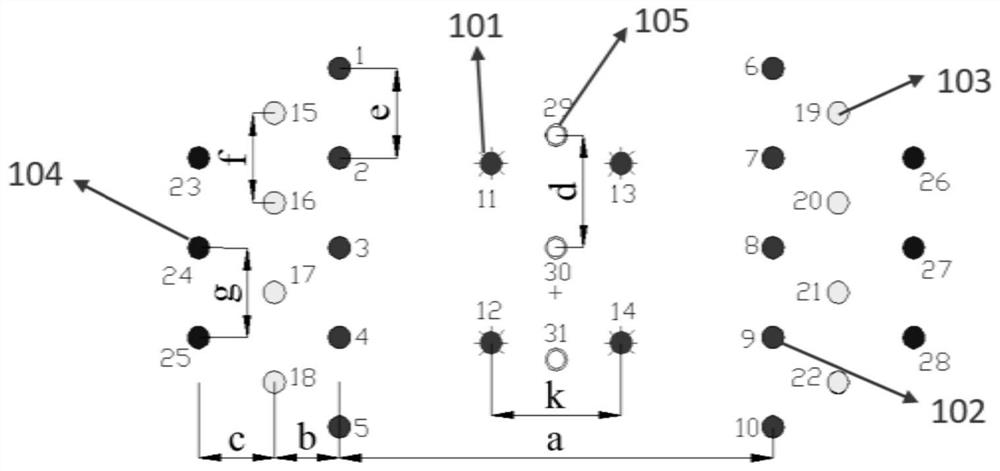
[0003] In terms of rock roadway cutting methods, multi-wedge cutting has been adopted in recent years, wherein (1) multi-wedge cutting adopts two-stage wedge-shaped or three-stage wedge-shaped compound Fewer advantages, using the wedge-shaped one-time + two-time + three times to increase the cutting depth step by step, but in the
coal mine roadway, the roadway section is generally 4 ~ 5.7m, the roadway width is limited, and the cutting cavity mouth can meet 0.8 ~1.2m, and the hole depth meets the design requirements of 2.4~3.0m, the rock drilling rig used for drilling is limited by the length of the
drill arm (3.5m~4.7m), resulting in the
wedge angle of the main
cut generally being 78~ 84°, 60-75° beyond the reasonable cutting angle of squint eyes, resulting in increased clamping effect of the bottom, thicker bulging phenomenon at the bottom, and reduced blasthole
utilization rate to 80%. The actual cutting depth is only 2.2-2.4m, and it is difficult to reach 3m above
deep hole cut(2) Straight-wedge mixed cutting adopts primary wedge + secondary wedge-straight
hybrid enhanced cutting, and primary wedge-straight mixed enhanced cut. Generally, the width of the primary groove is 0.8-1.5m, and the small groove causes the secondary groove to be free. The surface is small, and the
utilization rate of the straight hole is low under the action of deep clamping. The actual depth is only 2.4-2.6m. At the same time, the rate of large pieces of gangue is high, and the rate of excessive broken pieces is also high
In terms of peripheral smooth blasting, the conventional method adopts a large
diameter of 32mm without coupled light blasting, with a spacing of 300-400mm. Due to the large diameter of the charge coil and the small spacing, the blasting
energy density is high. When encountering weak and jointed rocks, it usually causes Over-excavation and under-excavation phenomena; in recent years, market standard specifications have been used: PVC pipes, ABS pipes, PPR
thermoplastic pipes, etc. The hole forms a two-way energy-concentrating tube at an angle of 180° on both sides of the tube, which can make the explosive energy produce a strong directional cutting effect along the cutting holes on both sides of the tube wall, weaken the blasting effect in other directions of the blast hole, and have a high success rate of light blasting, but due to the device Adopt the centralized charging method of installing 1-2 volumes of 500mm energy-concentrating tubes at the bottom of the hole with large-diameter
powder rolls of 32mm-35mm (the length of the explosive is 300-600mm).
Cutting effect occurs, the actual effective smooth
surface depth only accounts for 1 / 3 of the hole length, the smooth surface forming effect is poor, and due to the concentrated large-diameter and high-density charge at the bottom of the hole will cause a lot of over-undercutting
The use of small-diameter D-shaped tubes with an inner diameter of 27mm and an outer diameter of 32mm reduces the
energy density of the surrounding explosives, increases the distance between the surrounding holes to 600-800mm, reduces the number of drilling holes in the surrounding holes, and saves drilling time to a certain extent. , but for rock drilling rigs, the actual time saving is very limited (it only takes 2 minutes for a rock drilling rig to
drill a 3m deep hole, and the drilling efficiency is very high, which basically solves the problem of drilling speed and reduces the number of surrounding drilling holes 10 pieces, only save 20 minutes, time saving is limited); at the same time, because the energy is all concentrated on the directional cutting on both sides, there is no cutting effect along the radial direction of the roadway, resulting in more large pieces of gangue produced by peripheral eye blasting. unfavorable

