Rear-mounted ditcher soil splitter

A ditching machine, post-mounted technology, applied in the direction of excavation/covering ditches, land preparation machinery, agricultural machinery and tools, etc., can solve the problems that affect the safety of drivers, complex structure, easy to loose, etc., to achieve simple and fast process , good strength, and the effect of protecting safety

Pending Publication Date: 2022-05-13
葛伟岸 +1
View PDF1 Cites 0 Cited by
  • Summary
  • Abstract
  • Description
  • Claims
  • Application Information

AI Technical Summary

Problems solved by technology

Viewed from the front and rear of the cutter head of the trencher, the soil dividing plate is a V-shaped composite of left and right materials. The angle of the V-shape from front to back is the same. Viewed from the side, the soil divider is in a crescent-shaped curved arc arched upwards, and the curved edge of the lower side is slightly larger than the maximum rotation radius of the blade on the cutterhead; since the lower edge of the soil divider is curved, it is necessary to make the left and right two The lower edge of the curved plate is connected in a V shape, which can only be connected by welding or screws. The disadvantage is that the section shape of the soil divider from the front to the back is a V shape with the same angle. In dry soil and the speed of the cutter head is relatively high. In the state of ditching, many soil clods will be thrown forward during ditching operation, which will affect the safety of drivers; secondly, the curved structure is complex, it is difficult to produce by stamping, and the manufacturing process is not suitable for mass production, so welding can only be used , the process is troublesome and not firm; screw assembly is easy to cause loosening; during ditching operations, under the intense impact of high-speed soil blocks thrown by the cutter head, the lower edge of the soil plate is easy to crack and damage; Soil quality and humidity are different; because the V-shaped angle of the prior art soil divider is fixed, the dry hard soil and wet rotten soil are thrown upwards and collide with the fixed angle soil divider, and the soil divider divides the soil outward Inconsistent, wet and rotten fields are thrown close, and they tend to accumulate on the side of the ditch and cannot be scattered. Throw hard soil fields far away, and the soil on both sides of the ditch cannot be evenly covered with soil, and it will be thrown into the adjacent ditch to cause blockage; throw soil during ditching Not evenly distributed
In the prior art, there is also a structure that uses wing plates on both sides of the soil divider to adjust. Generally, the technical solution of hinge and screw adjustment is used, but its structure is complex and easy to loosen and damage.

Method used


Image

  • Rear-mounted ditcher soil splitter
  • Rear-mounted ditcher soil splitter
  • Rear-mounted ditcher soil splitter

Examples


Embodiment Construction

[0023] The present invention is described in further detail in conjunction with embodiment now.

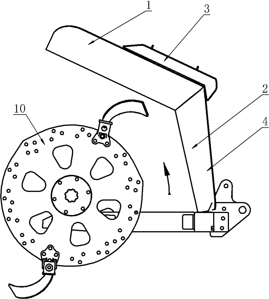
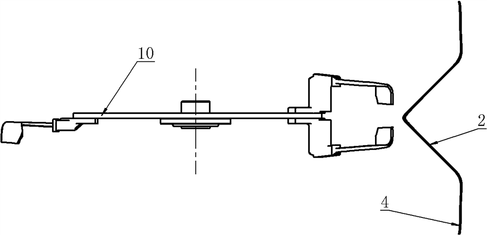
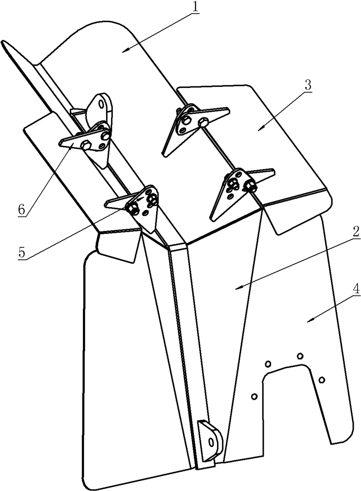
[0024] Such as Figure 1 to Figure 4 As shown, the present invention discloses a rear-mounted ditching machine soil divider. The soil divider is composed of two soil divider boards 1 and fenders 2 with different cross-sections. The whole piece of material is bent and made, and the cross-section is V-shaped when viewed from the front and rear; the fender 2 is located in front of the cutter head 10, and is also made of a whole piece of material bent. From a top view, the fender 2 The middle part of the cross-section is V-shaped, the V-shaped angle is small at the top and large at the bottom, and the depth of the V-shape is deep at the top and shallow at the bottom; The axial direction of the trencher cutterhead 10 is approximately parallel; the upper end of the V-shaped cross-section of the fender 2 is at the same angle as the V-shaped cross-section at the front end of the connecte...


PUM


Abstract

The invention discloses a rear-mounted ditcher soil splitter, which is arranged in front of a ditcher cutter head and consists of two soil splitting plates with sections in different shapes and a mud baffle. The middle part of the cross section of the front fender is V-shaped from an overlook angle, the V-shaped sharp bottom part protrudes towards the cutterhead, and a protection plate formed by bending from two sides of the V-shaped edge and transversely unfolding leftwards and rightwards is approximately parallel to the axial direction of the cutterhead of the ditcher; seen from the side face, the size of the V shape protruding backwards of the fender is large at the upper end and gradually small downwards, and the bottom of the V shape behind the fender and the bottom of the V shape below the soil dividing plate and adjacent to the rotating outer diameter of the cutterhead are straight lines. The soil dividing plate and the mud guard of the rear-mounted ditcher soil dividing device are both made of a whole piece of material, the strength is good, and the process is simple. Soil blocks thrown forwards by the cutter head are thrown leftwards and rightwards along the V-shaped angle of the fender towards the two sides along the bent arc and the protection plate and cannot be thrown forwards, and the safety of a driver can be fully protected.

Description

technical field [0001] The invention belongs to the field of agricultural machinery and relates to a rear-mounted ditching machine soil divider. Background technique [0002] The existing rear-mounted ditching machine matched with the four-wheel tractor is defined by the direction that the four-wheel tractor is in front and the ditching machine device is in the rear. Generally, a curved soil dividing plate is arranged on the upper front of the ditching machine cutter head , such as the patent No. CN201921215202.2 rear-mounted ditching machine soil-dividing wing, its function is to scatter the soil clods cut out by the cutter head from the ditch to both sides of the ditch. Viewed from the front and rear of the cutter head of the trencher, the soil dividing plate is a V-shaped composite of left and right materials. The angle of the V-shape from front to back is the same. Viewed from the side, the soil divider is in a crescent-shaped curved arc arched upwards, and the curved e...

Claims


Application Information

Patent Timeline
Patent Type & Authority Applications(China)
IPC IPC(8): A01C5/06A01B35/14A01B35/08A01B35/26A01B35/30A01B35/20
CPCA01C5/062A01B35/14A01B35/08A01B35/26A01B35/30A01B35/20
Inventor 葛玉明葛伟岸周雪梅葛桂萍
Owner 葛伟岸
Why Eureka
Try Eureka