
Dual-shaft unpacking and breaking device

A technology of crushing device and driving device, which is applied in the direction of grain processing, etc. It can solve the problems of easy emergency material jamming, inability to turn over immediately, and bulky volume, etc., and achieves the effects of easy maintenance and disassembly, easy material jamming and regurgitation, and high crushing efficiency

Pending Publication Date: 2020-06-05
NINGBO HUILONG MACHINERY CO LTD
View PDF0 Cites 2 Cited by
  • Summary
  • Abstract
  • Description
  • Claims
  • Application Information

AI Technical Summary

Problems solved by technology

[0002] In industrial production, many waste items can be crushed by crushing equipment and then recycled. However, traditional crushing equipment cannot deal with large waste such as large-scale automobile casing parts, various waste household appliances, and large-scale waste hardware. These bulky wastes are treated holistically or inefficiently
[0003] At the same time, traditional crushing equipment also has the following disadvantages: 1. Traditional crushing equipment usually drives the reducer through a motor, and then drives through a belt, with low torque and large torque ratio loss; 2. The amount of dust during the crushing process is large, and the equipment vibrates greatly , high noise, and poor working environment; 3. The equipment has low working efficiency and high energy consumption; 4. Most of the knives are made of medium carbon steel, which has high wear and tear and high replacement costs; 5. The types of crushed materials are single; 6. Huge, Large floor area; 7. Easy to get stuck in emergency, slow response, unable to turn over immediately, low efficiency of returning material

Method used


Image

  • Dual-shaft unpacking and breaking device
  • Dual-shaft unpacking and breaking device
  • Dual-shaft unpacking and breaking device

Examples


Embodiment Construction

[0022] The preferred embodiments of the present invention will be described in detail below in conjunction with the accompanying drawings, so that the advantages and features of the present invention can be more easily understood by those skilled in the art, so as to define the protection scope of the present invention more clearly.

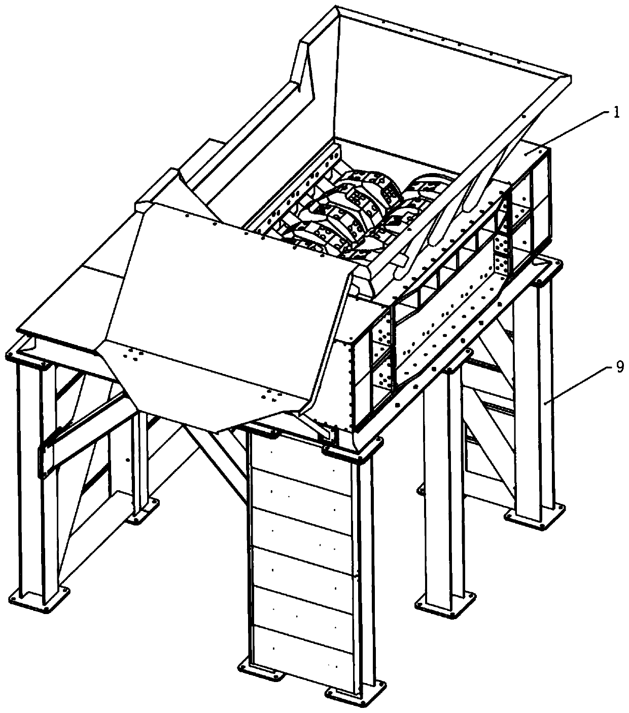
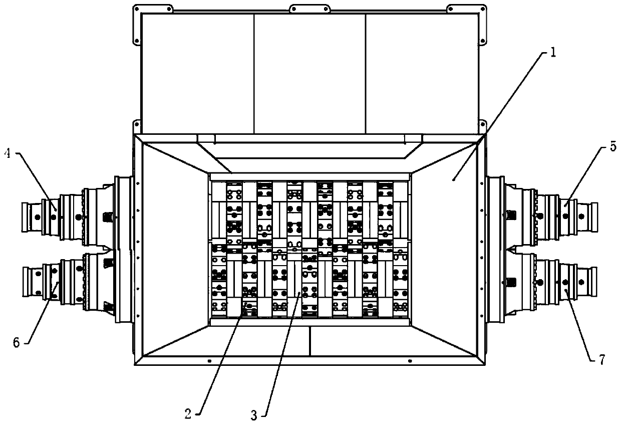
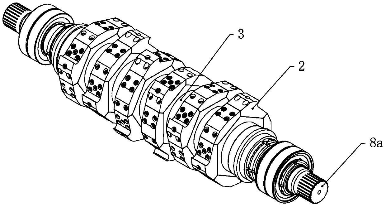
[0023] see Figure 1 to Figure 4 , the embodiment of the present invention includes:

[0024] A double-shaft unpacking and crushing device, comprising a casing 1, a stirring shaft and a driving device; the casing 1 is installed on a support frame 9; the stirring shaft includes a first stirring shaft 8a and a second stirring shaft 8b, and the first stirring shaft 8a Parallel to the second stirring shaft 8b, it passes through the inside of the box body 1. A plurality of cutters 2 are arranged at intervals along the axial direction on the two stirring shafts. The plurality of cutters 2 on the first stirring shaft 8a and the second stirring shaft 8b ...


PUM


Abstract

The invention discloses a dual-shaft unpacking and breaking device. The dual-shaft unpacking and breaking device comprises a box body, stirring shafts and a driving device, the stirring shafts comprise a first stirring shaft and a second stirring shaft mounted in the box body in a parallel penetrating manner, multiple tools are mounted on the stirring shafts at intervals in the axial direction, the tools on the first stirring shaft and the tools on the second stirring shaft are staggered in the axial direction, each tool comprises multiple tool bodies staggered on the corresponding stirring shaft in the radial direction, blade orientation of the tool bodies on the first stirring shaft and blade orientation of the tool bodies on the second stirring shaft are opposite, blades of the multipletool bodies on each stirring shaft form multi-row spiral line arranging in the axial direction, and the driving device comprises a first driving device directly connected with the first stirring shaft and a second driving device directly connected with the second stirring shaft. Through dual-shaft rollers, low-speed shearing and breaking can be achieved, a large material can be subjected to wholetreatment, and the advantages of being large in breaking strength, high in breaking efficiency, high in yield, low in energy consumption, clean and environment-friendly can be achieved.

Description

technical field [0001] The invention relates to the technical field of crushing devices, in particular to a biaxial unpacking and crushing device for crushing and decomposing large materials. Background technique [0002] In industrial production, many waste items can be crushed by crushing equipment and then recycled. However, traditional crushing equipment cannot deal with large waste such as large-scale automobile casing parts, various waste household appliances, and large-scale waste hardware. These bulky wastes are treated holistically or inefficiently. [0003] At the same time, traditional crushing equipment also has the following disadvantages: 1. Traditional crushing equipment usually drives the reducer through a motor, and then drives through a belt, with low torque and large torque ratio loss; 2. The amount of dust during the crushing process is large, and the equipment vibrates greatly , high noise, and poor working environment; 3. The equipment has low working ...

Claims


Application Information

Patent Timeline
IPC IPC(8): B02C18/14B02C18/16B02C18/18B02C18/24B02C25/00
CPCB02C18/0084B02C18/142B02C18/16B02C18/18B02C18/24B02C25/00
Inventor 陈戍寅
Owner NINGBO HUILONG MACHINERY CO LTD
Learn More