
Automatic gear-shifting wheel-hub motor of electric vehicle

A technology of automatic variable speed and wheel hub motors, which is applied in the direction of electric vehicles, motors, electric components, etc., can solve the problems of small adaptability, poor climbing ability and overload capacity, and large output torque, and achieve simple and compact structure and improve climbing The effect of large capacity and transmission torque

Active Publication Date: 2012-04-04
东阳市创升机电有限公司
View PDF2 Cites 7 Cited by
  • Summary
  • Abstract
  • Description
  • Claims
  • Application Information

AI Technical Summary

Problems solved by technology

This mode is simple in structure and easy to control, but in actual use, electric vehicles have different requirements for different road conditions; when driving normally, the hub motor requires fast speed and small output torque; when starting, climbing or large When the load is applied, the wheel hub motor is required to have a slow speed and a large output torque; its disadvantages are: first, because the motor is designed according to normal operating conditions, the output torque cannot be changed under the condition that the motor power remains constant. Slopes and heavy loads often make the motor run in an abnormal state, forcing the motor to work in a low-efficiency area, causing the motor to stall, heat up, or even stop rotating, causing impacts on important components such as the motor, battery, and controller, and shortening the life; Second, the climbing ability and overload ability are poor, the adaptation range is small, the operating efficiency is low, and the mileage is short
For this reason, many manufacturers and people of insight have carried out fruitful development and research, but no reasonable products have come out so far.

Method used


Image

  • Automatic gear-shifting wheel-hub motor of electric vehicle
  • Automatic gear-shifting wheel-hub motor of electric vehicle
  • Automatic gear-shifting wheel-hub motor of electric vehicle

Examples


Embodiment Construction

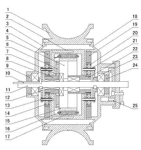
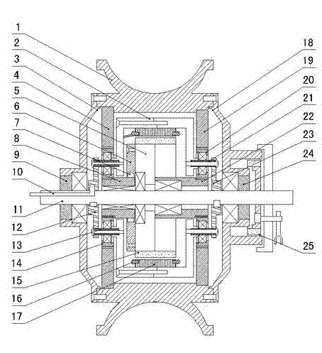
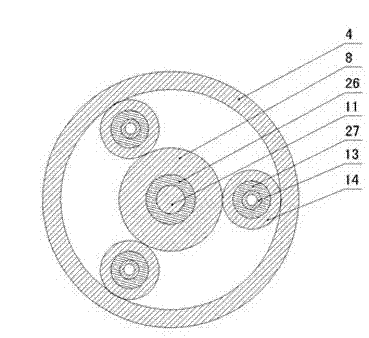
[0020] figure 1 , image 3 and Figure 4 As shown, the present invention creates the first specific embodiment of the automatic variable speed wheel hub motor for electric vehicles, which includes the hub 1, the left and right end covers 3, 18, the main shaft 11, the motor, and the left and right end covers 3, 18 and the wheel hub 1 form an airtight shell The outer shell is rotatably arranged on the main shaft 11 through the bearings arranged on the left and right end covers 3, 18, and the motor is installed in the outer shell. The motor includes an inner shell 2, an automatic clutch 5, a rotor magnet 15, The stator coil 16, the stator iron core 17, the automatic clutch 5 are rotatably installed on the main shaft 11 through the bearing, the rotor magnetic steel 15 is evenly distributed on the outer shell circumference of the automatic clutch 5, the stator iron core 17 is fixed on the rotor magnetic steel 15 On the corresponding inner casing 2 , the stator coil 16 is embedded...


PUM


Abstract

This invention discloses an automatic gear-shifting wheel-hub motor of an electric vehicle, which comprises wheel hubs (1), a left end cover, a right end cover (3, 18), a main shaft (11), and a motor, wherein the left end cover, the right end cover (3, 18) and the wheel hubs (1) compose an airtight shell body and can be rotationally arranged on the main shaft (11); the inner motor is mounted in the shell body; the inner motor comprises an inner shell body (2), an automatic clutch (5), rotor magnetic steels (15), a stator coil (16), and a stator iron core (17); the automatic clutch (5) is rotationally mounted on the main shaft (11); the rotor magnetic steels (15) are evenly distributed on the circumference of the outer shell body of the automatic clutch (5); the stator iron core (17) is fixed on the inner shell body (2) correspondingly to the rotor magnetic steels (15); the stator coil (16) is embedded on the stator iron core (17); two sides of the inner shell body (2) are correspondingly provided with a low-speed rotating mechanism and a high-speed rotating mechanism; by dint of a structure disclosed by this invention, the motor disclosed by this invention has advantages of simple and reasonable structures, large transmission torques, good climbing capacity and overloading capacity, high running efficiency, automatic gear shifting and the like.

Description

technical field [0001] The invention relates to a hub motor, in particular to a hub motor that can automatically change speed according to the speed. Background technique [0002] Electric vehicles are popular among consumers due to their energy saving and environmental protection, simple operation, convenient use, and low operating costs. At the same time, they have also received great attention from governments at all levels. Electric vehicles have entered a rapid development channel, and hub motors are in short supply. [0003] At present, the hub motors used in electric vehicles include DC motors, hubs, left and right hub covers, left and right half shafts, and reduction devices. The device includes a central gear fixed on the rotating shaft of the DC motor, planetary gears distributed in a star shape, and a ring gear arranged on the right hub cover. The planetary gears are rotatably arranged on the fixed shaft, and the fixed shaft is fixed on the motor cover of the DC m...

Claims


Application Information

Patent Timeline
Patent Type & Authority Applications(China)
IPC IPC(8): H02K7/10F16H1/32
CPCY02T10/641Y02T10/64
Inventor 马加良
Owner 东阳市创升机电有限公司
Learn More