Automatically and continuously adjustable centrifugal clutch

Inactive Publication Date: 2008-03-13
WU CHUN YI & PEI HSUAN WU
View PDF6 Cites 8 Cited by
  • Summary
  • Abstract
  • Description
  • Claims
  • Application Information

AI Technical Summary

Benefits of technology

[0007]A primary object of the present invention is to provide an automatically and continuously adjustable centrifugal clutch, wherein an angular acceleration response assembly senses a big change in rotating inertia when the throttle is instantaneously fully opened and the angular acceleration of the engine is increased instantaneously, and the angular acceleration response assembly will proceed a displacement in the opposite direction of the rotation of centrifugal clutch such that the returning force of the returning element become higher; the rotation speed of engine or centrifugal clutch has to be increased continuously to a level that the centrifugal force of the centrifugal weight is stronger enough to overcome the returning force of the returning element and centrifugally moving outward to engage with the driven unit, allowing the vehicle to have big torque and good initial acceleration at take-off.
[0008]Another object of the present invention is to provide an automatically and continuously adjustable centrifugal clutch, in which an angular acceleration response assembly senses a minor change in rotating inertia and does not move in a reverse direction when the throttle of vehicle is slowly accelerated at starting; the returning force of the returning element remaining unchanged (i.e., the original designed value), so that a centrifugal weight of the centrifugal clutch can engage with a driven unit at a low engine revolving speed (i.e., the original designed value), allowing the vehicle to start smoothly at normal fuel consumption.
[0011]In a vehicle or a mechanism using the automatically and continuously adjustable centrifugal clutch of the present invention, when the engine is started and instantaneously accelerated (i.e. the throttle of a vehicle is fully opened suddenly and instantaneously) and the rotation speed of clutch is instantaneously increased, the angular acceleration response assembly of the present invention is subjected to a big change in rotating inertia and moves in a reverse direction to tension the returning element and pull the centrifugal weight more tightly inwardly. At this point, the original designed centrifugal force of the centrifugal weight is not able to overcome the pull of the more tensioned returning element due to insufficient engine revolving speed. However, when the rotating speed of the base plate or centrifugal weight is continuously increased to let the centrifugal weights produce a higher centrifugal force sufficient to overcome the pull force of the more tensioned returning element, the centrifugal weight finally centrifugally moves outward to frictionally engage with and drive the driven unit to move at a high acceleration speed. When the centrifugal clutch of the present invention engages with the driven unit at the relatively high engine revolving speed, the vehicle or the mechanism may have a large starting or transmitting torque to enable good accelerating ability. On the other hand, when the engine is slowly accelerated (i.e. the throttle is actuated slowly), the engine output is stable and small and there is almost no any change in the rotating inertia, and therefore, the angular acceleration response assembly does not move reversely to pull the retuning element, the returning force of the retuning element remains the same as the original designed value and allowing the centrifugal weight to centrifugally move outward and engage with the driven unit at a low engine revolving speed (i.e., the original design value). In this case, the vehicle or the mechanism may be started smoothly.
[0012]With the present invention, a user may suddenly and instantaneously actuate the throttle fully opened at starting when a high initial acceleration or transmission torque is desired. And, when it is not necessary to quickly accelerate at starting, the user may slowly actuate the throttle of the vehicle or accelerate the mechanism smoothly.
[0013]In either case, the centrifugal clutch of the present invention can be automatically and continuously adjusted by throttle opening to get different engagement with the driven unit to have different acceleration rates. With this design, the vehicle or the mechanism may be differently accelerated at starting to meet the requirements of high acceleration performance or smoothly economical driving with normal fuel consumption.

Problems solved by technology

In either case, it is very time-consuming to disassemble and replace the clutch springs of the clutch assembly.
This is obviously inconvenient for a user to do so.
Meanwhile, it is still impossible to achieve automatic adjustment of the conventional centrifugal clutch for driving a vehicle to move at different initial acceleration.
Moreover, when the tensile strength of the clutch spring is adjusted higher to obtain a clutch engagement at a higher engine revolving speed and for the vehicle to have a big torque at starting, the fuel consumption of the vehicle increases at the same time.
In brief, it is impossible for a user to have clutch engagement at different engine revolving speeds as desired at any time.
The vehicle can only be moved forward at a fixed high engine revolving speed to consume high amount of fuel.
Therefore, with the conventional centrifugal clutch design, it is impossible for a vehicle to meet the requirements of good accelerating ability and economical driving at reduced fuel consumption at the same time.

Method used


Image

  • Automatically and continuously adjustable centrifugal clutch
  • Automatically and continuously adjustable centrifugal clutch
  • Automatically and continuously adjustable centrifugal clutch

Examples


Embodiment Construction

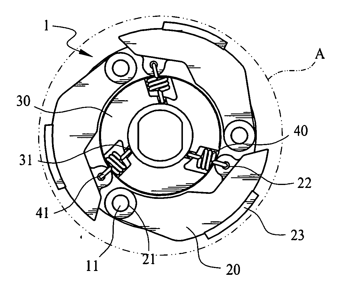
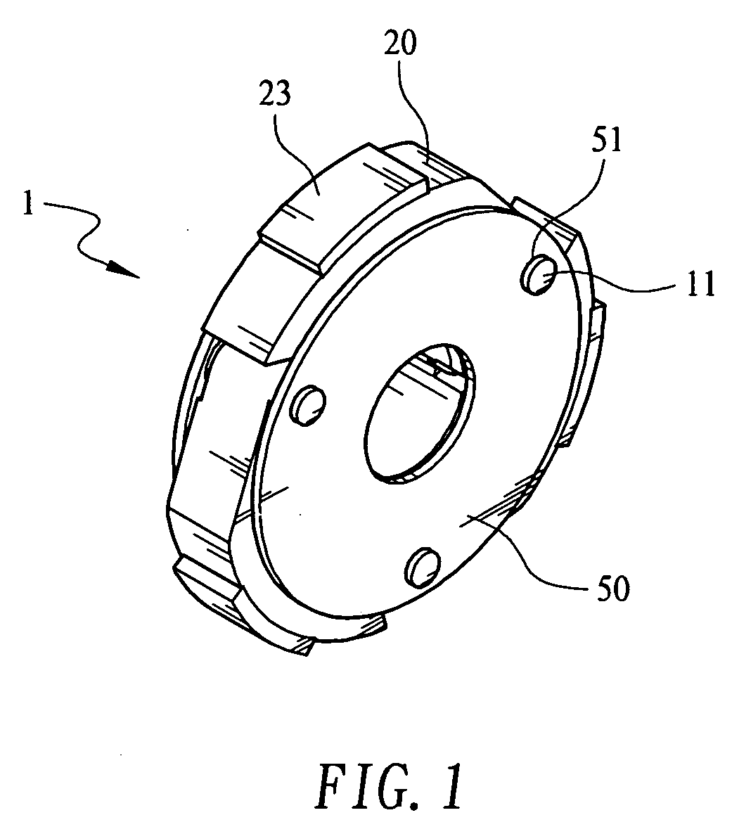
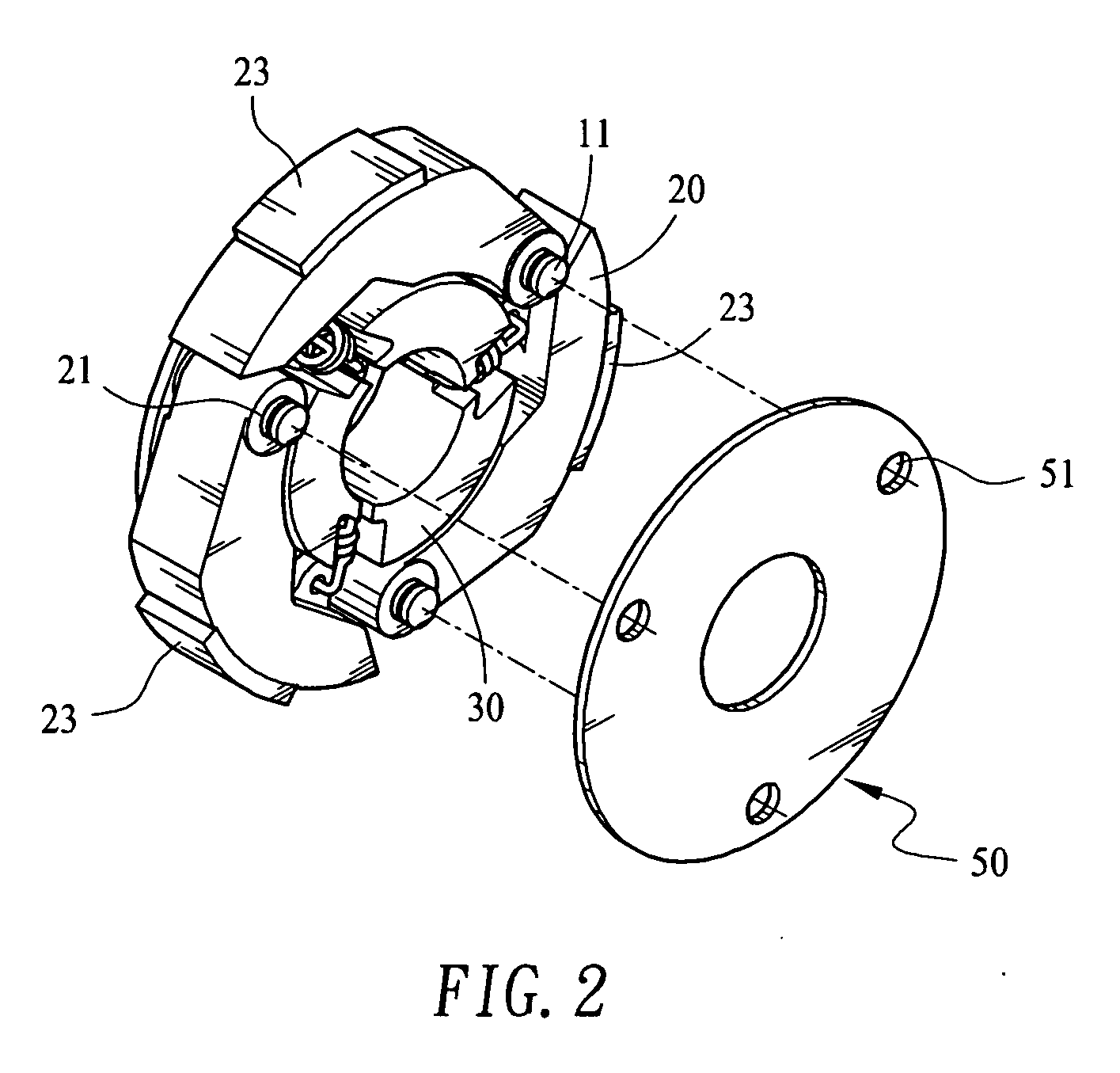
[0022]Please refer to FIGS. 1 to 3 that are assembled and exploded perspective views of an automatically and continuously adjustable centrifugal clutch 1 according to a first preferred embodiment of the present invention. For the purpose of conciseness, the present invention is also briefly referred to as “the centrifugal clutch 1” herein. As can be seen from FIG. 3, the centrifugal clutch 1 includes a base plate 10, on which at least one locating section 11 is provided; at least one centrifugal weight 20, which is provided at a first end with a connecting section 21 for engaging with the locating section 11 on the base plate 10, at an inner side of a second end opposite to the first end with an associating section 22, and at an outer surface with a driving face 23; at least one angular acceleration response assembly 30, on which at least one catch section 31 is provided corresponding to the associating section 22 of the centrifugal weight 20; and at least one returning element 40 h...


PUM


Abstract

An automatically and continuously adjustable centrifugal clutch has a base plate used to receive a power source; at least one centrifugal weight assembled to the base plate; at least one angular acceleration response assembly connected to the at least one centrifugal weight; and at least one returning element having two ends separately connected to one centrifugal weight and one angular acceleration response assembly. With these arrangements, a relatively high engine revolving speed at clutch engagement may be obtained by an instantaneously quickly increased acceleration rate at starting, so that a mechanism may have a large starting torque and good accelerating ability; and a relatively low engine revolving speed at clutch engagement may also be obtained by slow acceleration at starting to enable smooth starting at reduced fuel consumption.

Description

FIELD OF THE INVENTION[0001]The present invention relates to a centrifugal clutch for transmitting power, and more particularly to a centrifugal clutch in which centrifugal weights cooperate with one or more angular acceleration response assemblies, so that clutch engagement at different engine revolving speeds may be obtained simply through control of the throttle opening. That is, the clutch engagement may be achieved either at an instantaneously quickly increased acceleration to allow a high torque and good accelerating ability, or a slowly increased acceleration to allow smooth take-off and reduced fuel consumption.BACKGROUND OF THE INVENTION[0002]The currently available continuous variable transmission (CVT) for a vehicle generally includes a front pulley, a rear clutch assembly pulley, and a V-belt. The rear clutch assembly pulley includes a centrifugal clutch. Under a centrifugal effect, a wear pad of a centrifugal weight on the clutch is thrown outward to engage with a drive...

Claims


Application Information

Patent Timeline
IPC IPC(8): F16D43/18F16D43/24
CPCF16D43/18F16D2043/145
Inventor LIAN, NORMANWU, CHUN YI
Owner WU CHUN YI & PEI HSUAN WU
Why Eureka
Try Eureka