Novel millimeter wave broadband high-gain power amplifier

A technology of power amplifier and millimeter wave, which is applied in power amplifiers, improved amplifiers to expand bandwidth, etc., can solve the problems of inability to use differential circuits, sensitivity to process changes, and high design complexity, so as to reduce design complexity, simplify circuit structure, The effect of expanding the bandwidth

Active Publication Date: 2020-05-29
UNIV OF ELECTRONICS SCI & TECH OF CHINA
View PDF7 Cites 4 Cited by
  • Summary
  • Abstract
  • Description
  • Claims
  • Application Information

AI Technical Summary

Problems solved by technology

Traditional Twin Peaks G max -core amplifier through three-section transmission line TL 1 、TL 2 、TL 3 And transistors form a linear, lossless and reciprocal network to adjust the stability of the amplifier, such as Figure 7 As shown in (b), use the frequency characteristics of the transmission line to select the appropriate transmission line combination, so that the amplifier can achieve μ=1 at two frequency points at the same time, so as to achieve the purpose of expanding the bandwidth and obtaining a higher gain; however, in the actual use process , to achieve dual-G within the specified bandwidth range max peak, requires a combination of three transmission lines, which makes the design more complex; at the same time, TL 3 The length of the TL is long and the characteristic impedance is large, making the TL 3 The width is very narrow and sensitive to process changes, which further increases the difficulty of design; in addition, the structure cannot be applied to differential circuits, which greatly reduces the practicability of the structure in engineering

Method used


Image

  • Novel millimeter wave broadband high-gain power amplifier
  • Novel millimeter wave broadband high-gain power amplifier
  • Novel millimeter wave broadband high-gain power amplifier

Examples


Embodiment Construction

[0018] The present invention will be described in further detail below in conjunction with the accompanying drawings and embodiments.

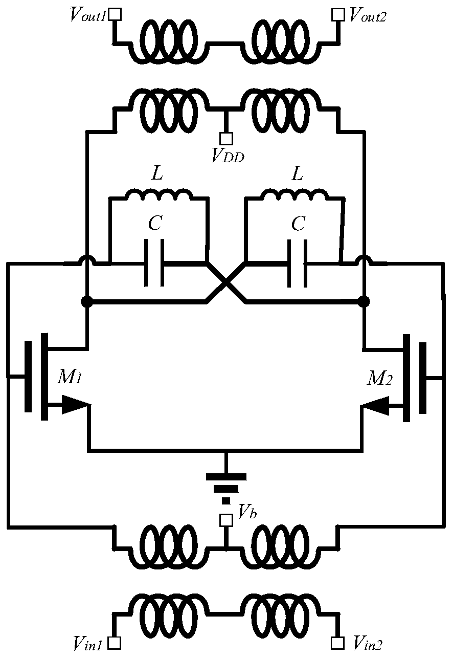
[0019] The present invention proposes a new broadband high-gain power amplifier structure, which changes the original single-ended circuit into a differential circuit, and uses capacitors and inductors to replace the three-section transmission line of the traditional structure; max At the same time, it simplifies the design complexity, improves the operating bandwidth of the amplifier, and enhances the practicability.

[0020] The schematic circuit diagram of the present invention is as figure 1 Shown: including: input coupler, differential common-source stage amplifier, first resonant circuit, second resonant circuit and output coupler; Wherein, described differential common-source stage amplifier is composed of transistor M 1 and transistor M 2 constitute, the transistor M 1 The gate of the transistor M 2 The first resonant circuit, the...


PUM


Abstract

The invention belongs to the field of high-frequency millimeter wave equipment and technologies, and particularly relates to a novel millimeter wave broadband high-gain power amplifier. The power amplifier mainly comprises a differential common-source amplifier and two LC resonance circuits connected to the gate and drain ends of the differential common-source amplifier in a crossed mode. According to the amplifier, the resonance circuit is connected to the gate and drain ends of the differential common source circuit in a crossed mode, a double-peak Gmax curve is obtained through the resonance circuit and the equivalent neutralization capacitance effect of the resonance circuit at high frequency, the bandwidth of the amplifier is greatly expanded, and the high-frequency gain is improved;as the resonance circuit formed by connecting the inductor and the capacitor in parallel replaces three sections of transmission lines in the traditional structure, the circuit structure is greatly simplified, and the design complexity is reduced; meanwhile, a traditional single-ended structure is expanded into a differential structure, and the output voltage swing is increased, so the output power is improved; therefore, the power amplifier with the structure is more beneficial to practical application in engineering.

Description

technical field [0001] The invention belongs to the field of high-frequency millimeter wave equipment and technology, and relates to a power amplifier, specifically a novel millimeter wave broadband high-gain power amplifier. Background technique [0002] In recent years, with the development of high-frequency millimeter-wave equipment and technology, various applications of high-frequency millimeter-wave, such as security screening, biotechnology, spectroscopy for material analysis, medical imaging, and high data rate communication, have attracted widespread attention. . The wider bandwidth allows these systems to employ simple modulation schemes, which greatly reduces front-end complexity and greatly reduces time-to-market. Amplifiers are one of the most important blocks in various mmWave systems, because the amplification of weak signals is crucial for the generation and detection of high frequency signals; however, when the amplifier operates at mmWave frequencies close...

Claims


Application Information

Patent Timeline
Patent Type & Authority Applications(China)
IPC IPC(8): H03F3/21H03F1/42
CPCH03F3/21H03F1/42
Inventor 康凯黄趾维吴韵秋赵晨曦刘辉华余益明
Owner UNIV OF ELECTRONICS SCI & TECH OF CHINA
Why Eureka
Try Eureka