
Wireless temperature online monitoring and early warning system

A monitoring and early warning, wireless temperature technology, applied in the field of wireless temperature online monitoring and early warning system, can solve the problem that the temperature measurement technology cannot achieve remote, real-time, online monitoring, cannot meet the long-term stability and safety needs of the power industry, and the temperature measurement module technology level is low. and other problems, to achieve the effect of convenient and flexible installation, high reliability, and guaranteed reliability

Inactive Publication Date: 2020-05-29
GUIZHOU POWER GRID CO LTD
View PDF15 Cites 1 Cited by
  • Summary
  • Abstract
  • Description
  • Claims
  • Application Information

AI Technical Summary

Problems solved by technology

The switchgear is widely used in the power system. It is an important equipment in the power transmission and distribution system. Poor contact of static contacts, coupled with long-term high current, aging of contacts and other factors can easily lead to increased contact resistance, resulting in long-term heating, excessive temperature rise of contacts, and eventually high-voltage cabinet burnout accidents
[0005] 2) The cable connector is faulty
[0007] The temperature measurement modules used in most of the existing online monitoring products have a low level of technology and cannot meet the long-term stability and security needs of the power industry. For the goal of "unattended", the existing temperature measurement technology cannot achieve remote, Real-time, online monitoring requirements, its safe operation is worrying. Traditional infrared, optical fiber and active wireless temperature measurement systems have certain technical defects in terms of safety, reliability, economy, and real-time performance

Method used


Image

  • Wireless temperature online monitoring and early warning system
  • Wireless temperature online monitoring and early warning system

Examples


Embodiment Construction

[0032] Hereinafter, preferred embodiments of the present invention will be described in detail with reference to the accompanying drawings. It should be understood that the preferred embodiments are only for illustrating the present invention, but not for limiting the protection scope of the present invention.

[0033] In the description of the present invention, it should be understood that the terms "longitudinal", "length", "circumferential", "front", "rear", "left", "right", "top", "bottom", "inner ", "outside" and other indicated orientations or positional relationships are based on the orientations or positional relationships shown in the drawings, which are only for the convenience of describing the present invention and simplifying the description, rather than indicating or implying that the referred device or element must have a specific Orientation, construction and operation in a particular orientation, therefore should not be construed as limiting the invention.

...


PUM


Abstract

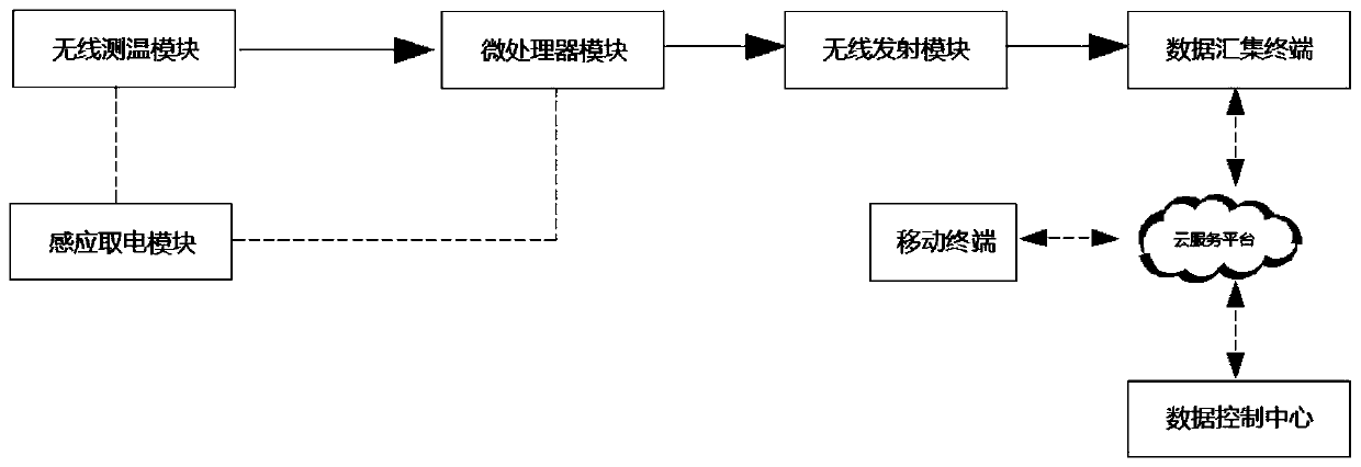
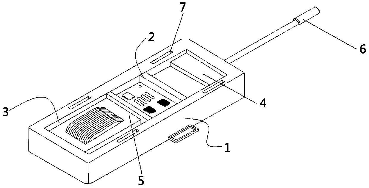
The invention discloses a wireless temperature online monitoring and early warning system which comprises a plurality of wireless sensors, a data collection terminal, a cloud service platform and a data control center. An induction power taking module is electrically connected with a wireless temperature measuring module and supplies power to the wireless temperature measuring module, the wirelesstemperature measuring module is used for measuring the surface temperature of measured equipment and outputting a temperature signal to a microprocessor module, and the microprocessor module outputsthe temperature signal data to the data collection terminal through a wireless transmitting module; the data collection terminal uploads the data to the cloud service platform, and the data control center is in communication connection with the cloud service platform. The wireless temperature online monitoring and early warning system is a wireless temperature sensing solution based on a passive wireless sensing technology, the temperature measuring module and background communication are completely physically isolated, wireless networking is adopted, temperature measuring nodes can be flexibly increased and decreased, and the system is safe, convenient, real-time, efficient and more suitable for monitoring the temperature rise of the electrical contact in a high-voltage complex magnetic field environment.

Description

technical field [0001] The invention relates to the technical field of electric power temperature measurement, in particular to a wireless temperature online monitoring and early warning system. Background technique [0002] According to the analysis of power accidents, the fire caused by the failure of power equipment caused a large area of ​​power equipment to be burned, resulting in forced shutdown, unable to resume production in a short period of time, resulting in major economic losses. Through the analysis of the accident, the direct cause of the fire is the poor quality of the intermediate head in the power equipment, the crimping head is not tight, and the contact resistance is too large. In addition, factors such as long-term high current and aging of the contact head can easily increase the contact resistance. Large, resulting in long-term heating, excessive temperature rise of the contacts, and even the eventual burning of high-voltage cabinets and cables. [000...

Claims


Application Information

Patent Timeline
Patent Type & Authority Applications(China)
IPC IPC(8): G01K1/02G01K1/08G01K1/14G01K1/022G01K1/024G01K1/143
CPCG01K1/024G01K1/026G01K1/028G01K1/08G01K1/143
Inventor 宁楠黎华龙狄睿冯泳王师国杨旭戴堃刘兴艳罗金龙杜林
Owner GUIZHOU POWER GRID CO LTD
Learn More