Two-stage compression sliding-vane-type vacuum pump with asymmetric cylinder profiles

A two-stage compression, asymmetrical technology, applied in the direction of rotary piston pumps, pump combinations for elastic fluid rotary piston type/swing piston type, pumps, etc., can solve the problem of not significantly improving the volume ratio of the vacuum pump and increasing the flow rate and other problems to achieve the effect of enriching types, reducing clearance volume and improving volumetric efficiency

Pending Publication Date: 2020-05-29
CHINA UNIV OF PETROLEUM (EAST CHINA)
View PDF1 Cites 0 Cited by
  • Summary
  • Abstract
  • Description
  • Claims
  • Application Information

AI Technical Summary

Problems solved by technology

[0003] With the expansion of the application field of the vacuum pump, the requirements for its vacuum degree are gradually increased, so the vacuum pump is required to have a larger internal volume ratio; the patent with the publication number CN 209671208 U proposes a double-chamber sliding vane compressor cylinder, which The cavity profile of the secondary helix structure realizes the asymmetric double-cavity structure, increases the flow rate of the liquid to be transported, and improves the force of the sliding vane; but the form of single-stage compression and multi-cavity parallel connection does not significantly improve the vacuum pump. internal volume ratio

Method used


Image

  • Two-stage compression sliding-vane-type vacuum pump with asymmetric cylinder profiles
  • Two-stage compression sliding-vane-type vacuum pump with asymmetric cylinder profiles
  • Two-stage compression sliding-vane-type vacuum pump with asymmetric cylinder profiles

Examples


Embodiment Construction

[0059] The present invention will be further described below in conjunction with accompanying drawing.

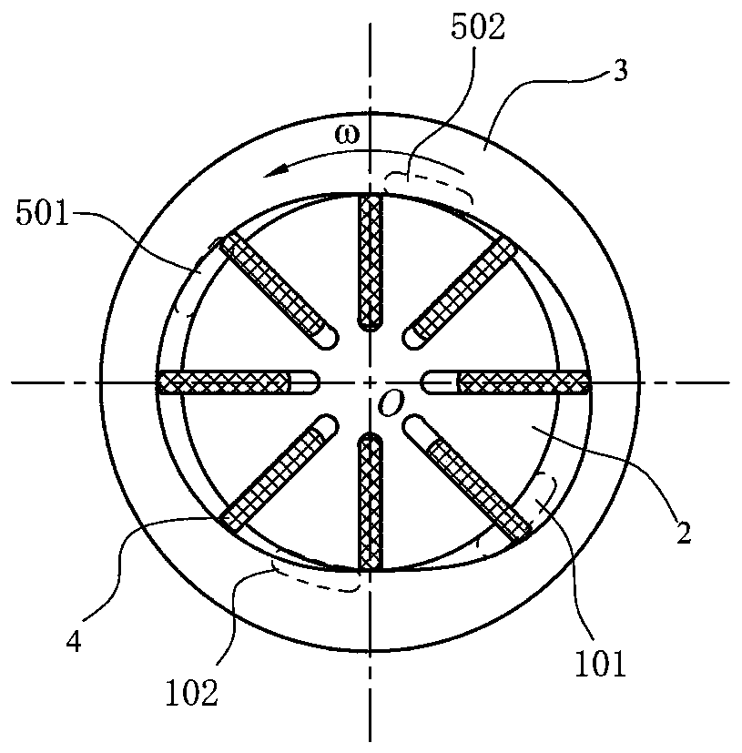
[0060] Such as figure 1 As shown, it is a component diagram of a two-stage compression vane vacuum pump with asymmetric cylinder profile, including: front cover (1), rotor (2), cylinder (3), vane (4) and rear end Cover (5). The rotor (2) is symmetrically provided with m centripetal or eccentric sliding slots, 6≤m≤12, and a sliding piece (4) is assembled in each sliding slot.

[0061] Such as figure 2 As shown, it is an axial view of a two-stage compression vane vacuum pump with an asymmetrical cylinder profile. Port (502); the axial projection of the secondary suction port (501) on the cylinder (3).

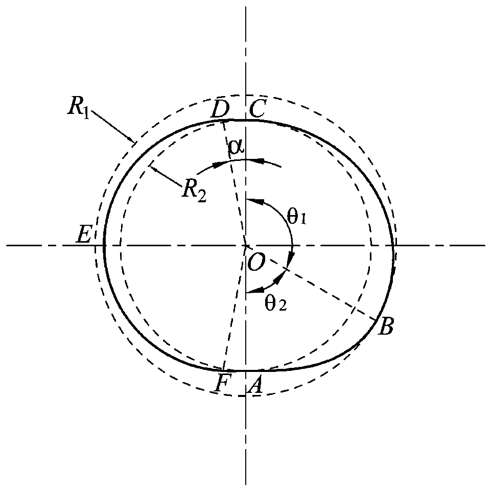
[0062] Such as image 3 As shown, it is a profile line diagram of the cylinder (3) of a two-stage compression vane vacuum pump with cylinder profile asymmetry. The contour line diagram of the cylinder (3) is formed as follows: Establish a polar coordinate system with th...


PUM


Abstract

The invention discloses a two-stage compression sliding-vane-type vacuum pump with asymmetric cylinder profiles. The two-stage compression sliding-vane-type vacuum pump is composed of a front end cover (1), a rotor (2), a cylinder (3), sliding vanes (4) and a rear end cover (5); profiles of the cylinder (3) are composed of five different curves, and first derivatives are continuous and second derivatives are continuous; in the working process, two asymmetric cavities with different volumes are formed between the front end cover (1), the cylinder (3), the rear end cover (5) and the rotor (2), gas finishes a first-stage compression process in a first-stage cavity (301), and then enters a second-stage cavity (302) for second-stage compression to realize two-stage compression; and a first airsucking opening (101) and a second exhaust opening (102) are formed in the front end cover (1), and a first exhaust opening (502) and a second air sucking opening (501) are formed in the rear end cover (5). The two-stage compression sliding-vane-type vacuum pump has a larger interior volume specific ratio, improves the vacuum degree, can further reduce waste work at the same time, and reduce the clearance volume.

Description

technical field [0001] The invention relates to a vacuum pump, in particular to a two-stage compression sliding vane vacuum pump with asymmetric cylinder profiles. Background technique [0002] The sliding vane vacuum pump is a positive displacement vacuum pump. The sliding vane vacuum pump is mainly composed of an end cover, a pump body, a rotor and a sliding vane. The rotor is installed in the pump chamber, and the sliding vanes are fitted in the groove of the rotor. In the process, under the action of centrifugal force, the sliding vane is thrown out of the chute so that it clings to the inner wall of the cylinder and rotates with the rotor, forming a periodically changing closed working chamber between the suction and exhaust end covers, sliding vanes, rotor and cylinder. Complete the gas suction, compression and discharge process. It has the advantages of high efficiency, small size, ability to suck impurity gas, and simple structure, and is widely used in metallurgy, ...

Claims


Application Information

Patent Timeline
Patent Type & Authority Applications(China)
IPC IPC(8): F04C23/00F04C18/344F04C25/02
CPCF04C18/3441F04C23/001F04C25/02F04C2240/10F04C2250/30
Inventor 王君刘译阳董丽宁谈庆鹏陈志凯武萌
Owner CHINA UNIV OF PETROLEUM (EAST CHINA)
Why Eureka
Try Eureka