
Oil leading-out cooling structure of large-pumping-speed rotary vane pump

A cooling structure and technology of rotary vane pumps, which are applied in the sealing device of piston pumps, components of pumping devices for elastic fluids, rotary piston type/oscillating piston type pump components, etc., and can solve unsatisfactory cooling effects, etc. problem, to achieve the effect of easy structure, remarkable effect, and ultimate vacuum degree improvement

Pending Publication Date: 2022-04-08
BEIJING BEIYI WOOSUNG VACUUM TECH
View PDF6 Cites 0 Cited by
  • Summary
  • Abstract
  • Description
  • Claims
  • Application Information

AI Technical Summary

Problems solved by technology

This method is simple and cost-effective, but it is more suitable for small pumping speed rotary vane pumps. For large volume high pumping speed rotary vane pumps, the cooling effect is not ideal due to the large oil tank.

Method used


Image

  • Oil leading-out cooling structure of large-pumping-speed rotary vane pump
  • Oil leading-out cooling structure of large-pumping-speed rotary vane pump
  • Oil leading-out cooling structure of large-pumping-speed rotary vane pump

Examples


Embodiment Construction

[0041] The following examples are intended to illustrate the present invention, but not to limit the scope of the present invention.

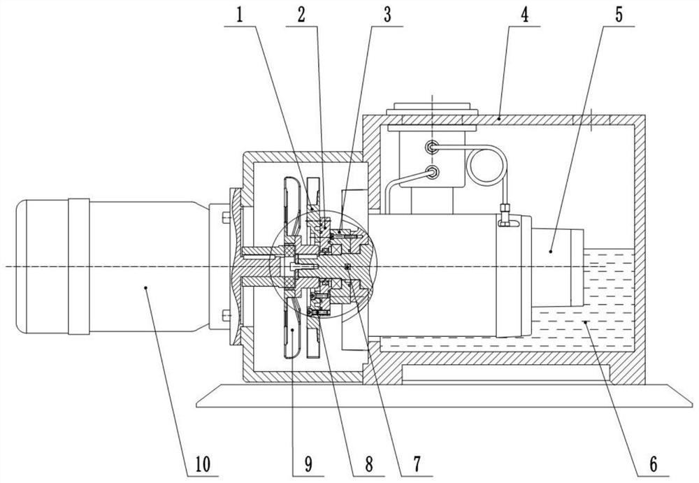
[0042] An oil extraction cooling structure of a high pumping speed rotary vane pump, the high pumping speed rotary vane pump includes a motor 10, an oil tank 4 and a pump core 5, and the pump core 5 includes a rotor, an oil pump rotary vane 7 and other components;

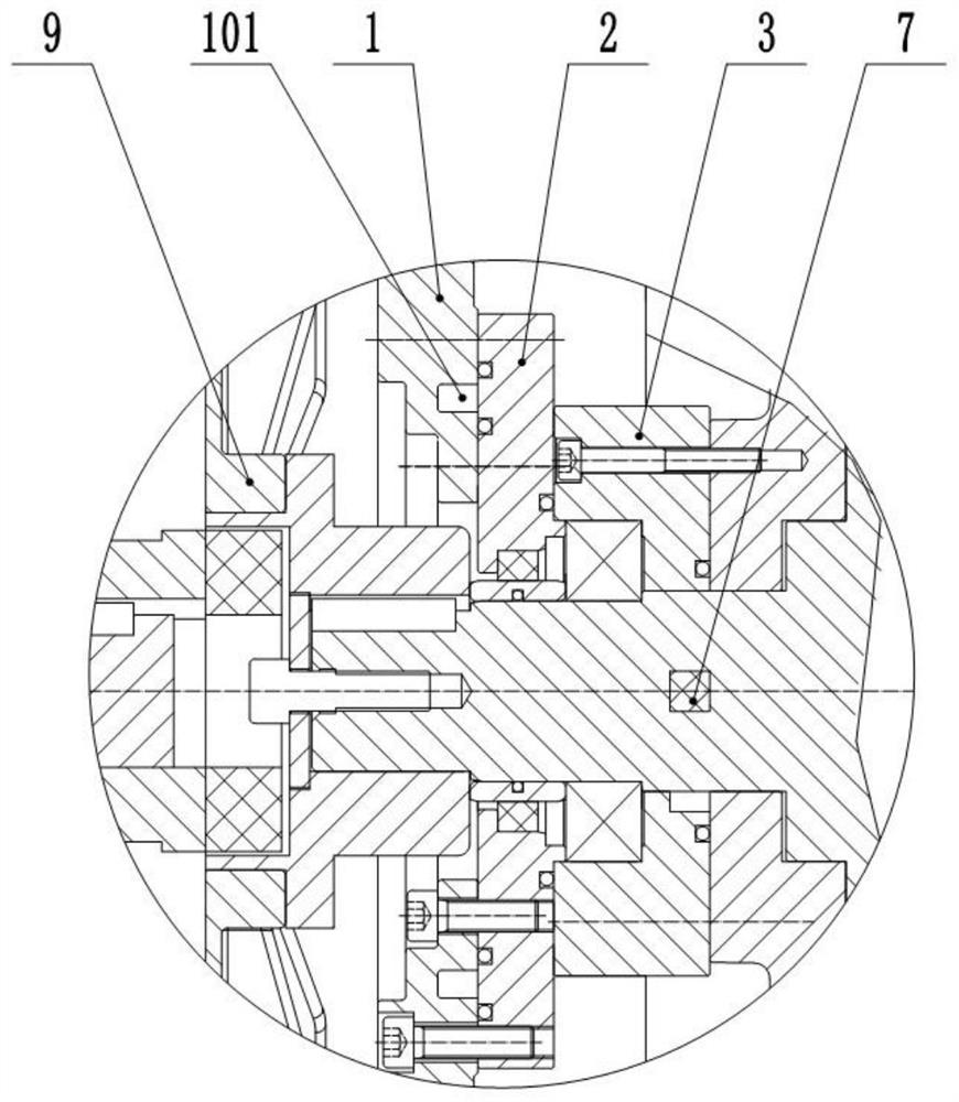
[0043] The extended end of the rotor is mounted on the bearing seat 3 through a bearing, and an oil pump groove is provided in the center of the pump core side of the bearing seat 3 for the rotation of the oil pump rotary vane 7; the other side of the bearing seat 3 is sealed and connected The bearing gland 2, the other side of the bearing gland 2 is sealed and connected to the oil cooling fin 1;

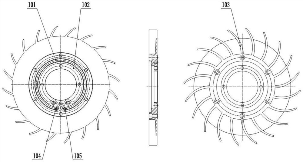
[0044] Wherein, a C-shaped oil groove 101 is provided on one side of the oil cooling fin 1 connected to the bearing press cover 2; a fan 9 is installed on the other side of the oil coolin...


PUM


Abstract

The invention relates to an oil leading-out cooling structure of a high-pumping-speed rotary vane pump, the high-pumping-speed rotary vane pump comprises a motor, an oil tank and a pump core, and the pump core comprises a rotor and an oil pump rotary vane; the extending end of the rotor is installed on a bearing seat through a bearing, and an oil pump groove is formed in the center of the pump core side of the bearing seat and can allow an oil pump rotary vane to rotate. The other side of the bearing seat is hermetically connected with a bearing gland, and the other side of the bearing gland is hermetically connected with an oil cooling radiating fin; a C-shaped oil groove is formed in one side, connected with the bearing gland, of the oil-cooling radiating fin; and a fan is mounted on the other side of the oil cooling radiating fin. On the basis of air cooling heat dissipation, after pump oil is cooled through the oil tank, the oil cooling heat dissipation fins are introduced for reinforced cooling firstly, then the pump oil enters the pump core for circulation, the cooling effect is good, a cooling water circulation system does not need to be additionally arranged, cost is saved, and simplicity and convenience are achieved.

Description

technical field [0001] The invention relates to a high pumping speed rotary vane pump, in particular to an oil extraction cooling structure of the high pumping speed rotary vane pump. Background technique [0002] Rotary vane oil-sealed mechanical pump, referred to as rotary vane pump, is a variable capacity vacuum pump that relies on vacuum pump oil to seal, lubricate and cool. After the rotary vane pump is started, the temperature of the pump core gradually increases, and the temperature of the pump oil also increases. The higher the oil temperature, the higher the saturated vapor pressure of the oil, and the higher the ultimate pressure of the pump, which directly affects the rotary vane pump. pumping performance. Therefore, the rotary vane pump needs to take certain cooling measures to avoid excessive oil temperature. When the pump is working, the vacuum pump oil circulates in the pump core and the oil tank. The traditional cooling method is to cool the oil tank. Gener...

Claims


Application Information

Patent Timeline
Patent Type & Authority Applications(China)
IPC IPC(8): F04C29/00F04C29/04F04C27/00F04C25/02
Inventor 朱秀明郑春军付惺玥
Owner BEIJING BEIYI WOOSUNG VACUUM TECH
Learn More