
Shot peening machine

A shot peening machine and shot peening technology, which is applied in the direction of abrasive jetting machine tools, used abrasive processing devices, abrasives, etc., can solve the problems of poor shot peening effect of tubular objects, so as to improve the shot peening effect and improve practicability , The effect of reducing the cost of shot peening

Active Publication Date: 2020-05-29
山东吉华重工机械有限公司
View PDF8 Cites 3 Cited by
  • Summary
  • Abstract
  • Description
  • Claims
  • Application Information

AI Technical Summary

Problems solved by technology

[0010] Regarding the shot blasting machine, in Shen Guoliang's "Coating Industry", several very practical shot blasting machines and their control systems are introduced; In the Chinese utility model patent whose application number is 2012201488127, it includes a shot blasting chamber and a dust collector; The cabinet is electrically connected to the shot blasting tank, the top of the shot blasting tank is equipped with a sealed mushroom head valve, and the bottom of the shot blasting tank is equipped with a shot blasting valve; the top of the dust collector is equipped with a dust removal fan, and the bottom of the dust collector is equipped with a waste bucket ;The waste barrel is connected to the shot blasting room through the air duct; the utility model has a simple structure and ingenious design, and is controlled by a microcomputer, so as to meet the requirements of low-pressure spraying operations of different abrasives; Shot peening treatment is not involved, and the shot peening effect of the tubular object is not good, which makes this technical solution have defects

Method used


Image

  • Shot peening machine
  • Shot peening machine
  • Shot peening machine

Examples


Embodiment approach

[0035] As a specific embodiment of the present invention, a No. 1 channel 331 and a group of No. 1 holes 332 are opened on the No. 1 rod 33 , and each No. 1 hole 332 communicates with the No. 1 channel 331 ; the sleeve 53 There is a No. 1 slot on the top, and the No. 1 slot is connected with a push plate 55 by a spring, and a group of protrusions 56 are arranged on the end surface of the push plate 55 close to the tubular object; the air flow generated by the movement of the push block 51 passes through the No. 1 channel 331 and a group of No. 1 holes 332 act on the push plate 55 to prevent the tubular object from falling off from the sleeve 53; by setting the push plate 55, a group of protrusions 56 on the push plate 55 are used to increase the distance between the inner wall of the tubular object and the tubular object. friction, which eliminates the possibility of the tubular object breaking away from the sleeve 53, reduces the subsequent processing of the tubular object aga...


PUM


Abstract

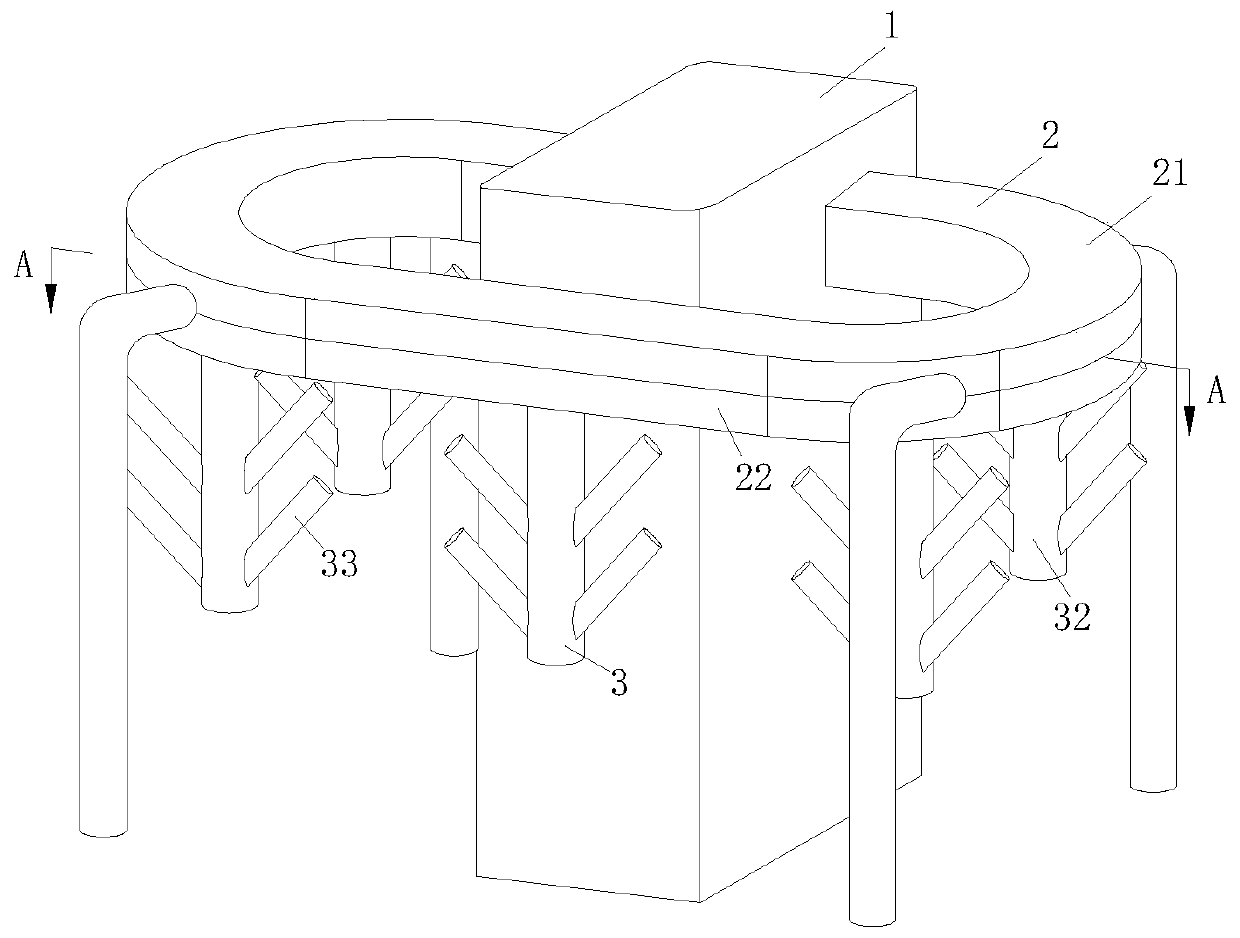
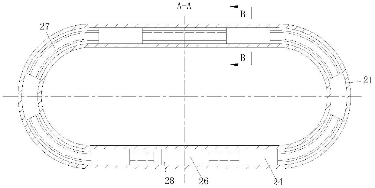
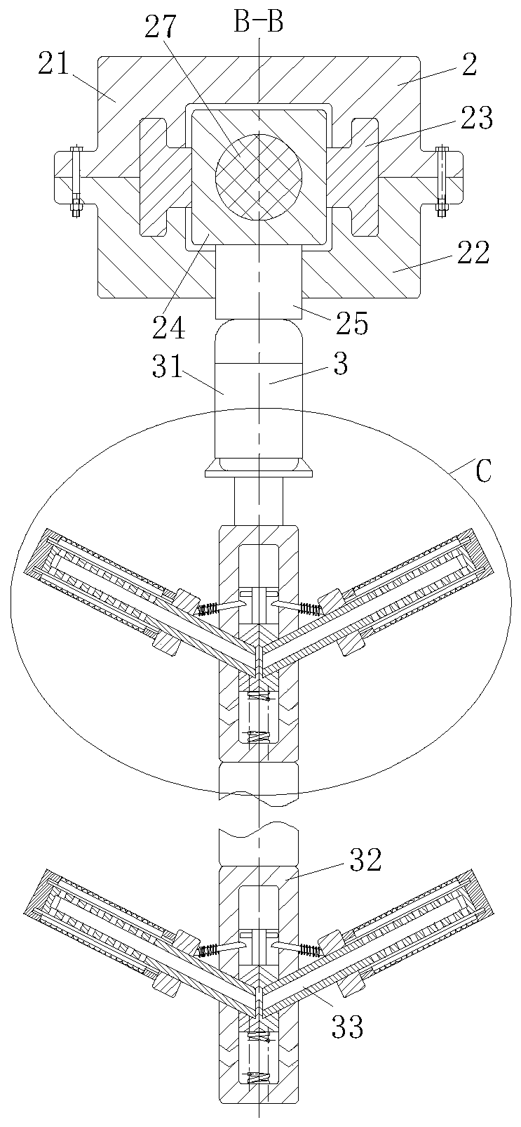
The invention belongs to the technical field of shot peening equipment, in particular to a shot peening machine. The shot peening machine comprises a shot peening box, an operation unit, a working unit and a controller, wherein the controller is used for controlling the shot peening machine to work; the operation unit comprises a groove-shaped upper supporting plate, a groove-shaped lower supporting plate, a sliding block, an installation block, a connecting shaft, a forward and reverse rotation motor, an elastic first lead screw and a fixing block; and the working unit comprises a first motor, a first shaft and a first rod. Under the action of the forward and reverse rotation motor, the fixing block passes through the shot peening box twice, so that the shot peening times of the shot peening box on a tubular object are increased, and the shot peening effect of the tubular object is improved; and meanwhile, when the working unit penetrates through the shot peening box, the first motoris used for driving the first shaft to rotate, so that the tubular object is subjected to shot peening treatment without dead corners, the dead corners, which are not subjected to shot peening treatment and need to be treated again in the later period, of the tubular object are reduced, the shot peening cost is reduced, and the practicability of the shot peening machine is improved.

Description

technical field [0001] The invention belongs to the technical field of shot blasting equipment, in particular to a shot blasting machine. Background technique [0002] The shot blasting machine is different from the domestic sand blasting machine. Its process principle is to use the impact of the high-speed moving shot flow on the metal surface to generate a plastic cyclic strain layer on the surface, which leads to favorable changes in the microstructure of the layer and The residual compressive stress field is introduced into the surface layer. The microstructure of the surface layer and the residual compressive stress field are two strengthening factors to improve the fatigue fracture and stress corrosion (hydrogen embrittlement) fracture resistance of metal parts. As a result, the reliability and durability of the parts are improved. At the same time, the oxide scale and dirt on the metal surface will be taken away during the impact of the high-speed projectile flow on t...

Claims


Application Information

Patent Timeline
Patent Type & Authority Applications(China)
IPC IPC(8): B24C3/08B24C3/10B24C9/00
CPCB24C3/10B24C3/083B24C9/00
Inventor 程顺平陈杰
Owner 山东吉华重工机械有限公司
Learn More