
High-humidity N2 generator

A generator and high-humidity technology, applied in chemical instruments and methods, mixers, mixing methods, etc., can solve the problems of not being able to meet the needs of use, not allowing nitrogen moisture, uneven grinding rate, etc., to achieve simple structure and easy operation Convenience, guaranteed stability and durability

Pending Publication Date: 2020-05-29
深圳融科科技有限公司
View PDF0 Cites 0 Cited by
  • Summary
  • Abstract
  • Description
  • Claims
  • Application Information

AI Technical Summary

Problems solved by technology

[0002] Chemicals with particles (abrasives) in the microelectronics industry (abrasive fluid, sandblasting fluid, cutting fluid, polishing fluid, etc.), in order to avoid the liquid being thin on the side of the container when the liquid level is settling during use, and because the general prevention of pollution will Nitrogen is used as nitrogen blanket, and nitrogen is generally 99.99% dry; in order to prevent the liquid surface from settling, particles (abrasives) / abrasives are precipitated on the surface of the container, most of these particles are in the range of 10-2000nm, because of the Van DerWarr force Changes in the surrounding potential will cause these dry particles to gather, and when they fall into the liquid surface, large particle deposits will form, which will change the original particle distribution of the liquid, and even cause lapping, polishing scratches , missing, and uneven grinding rate
At the same time, the nitrogen humidifier must control the humidity, and the nitrogen moisture is not allowed to precipitate into the liquid to dilute the liquid, resulting in changes in the concentration of chemicals
It must be sprayed with fine mist particles (within 1 μm), and the RH (relative humidity) is required to be in the high humidity range of 95-99% RH. The existing nitrogen humidification device has limitations and cannot meet the needs of use

Method used


Image

  • High-humidity N2 generator
  • High-humidity N2 generator

Examples


Embodiment Construction

[0017] In order to make the purpose, technical solutions and advantages of the embodiments of the present invention clearer, the technical solutions in the embodiments of the present invention will be clearly and completely described below in conjunction with the accompanying drawings in the embodiments of the present invention. Obviously, the described embodiments It is some embodiments of the present invention, but not all of them. Based on the implementation manners in the present invention, all other implementation manners obtained by persons of ordinary skill in the art without creative efforts fall within the protection scope of the present invention. Accordingly, the following detailed description of the embodiments of the invention provided in the accompanying drawings is not intended to limit the scope of the claimed invention, but merely represents selected embodiments of the invention. Based on the implementation manners in the present invention, all other implement...


PUM

PropertyMeasurementUnit
Inner diameteraaaaaaaaaa

Abstract

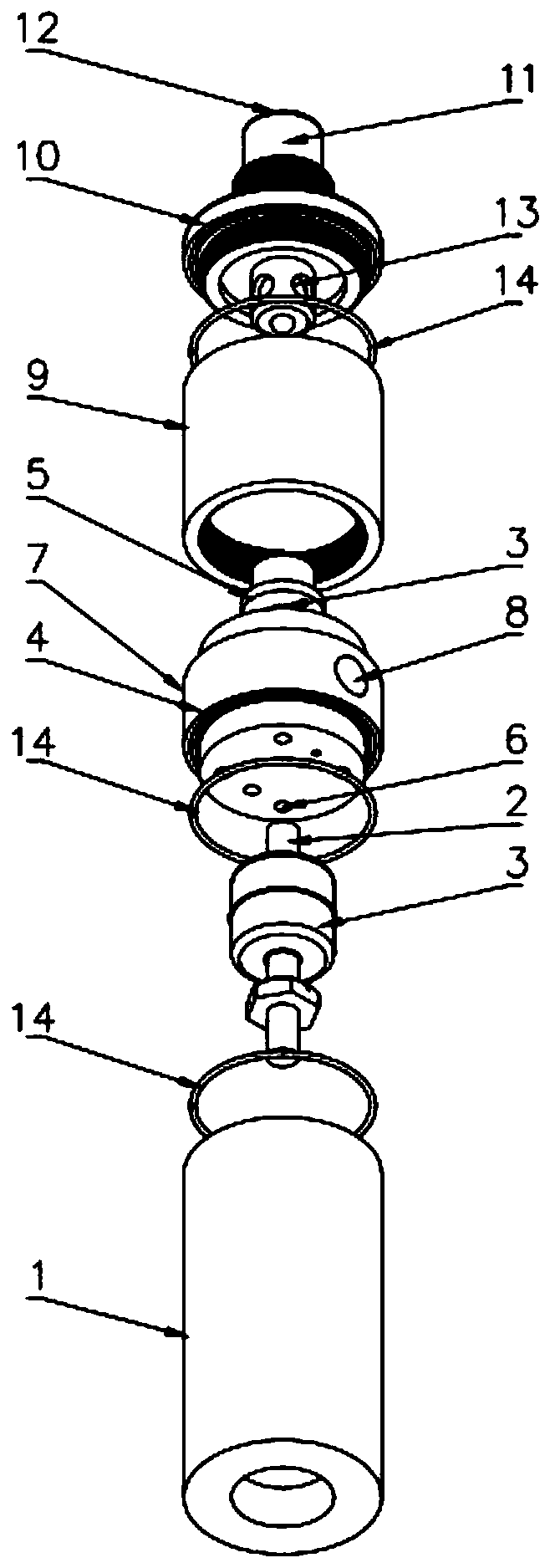
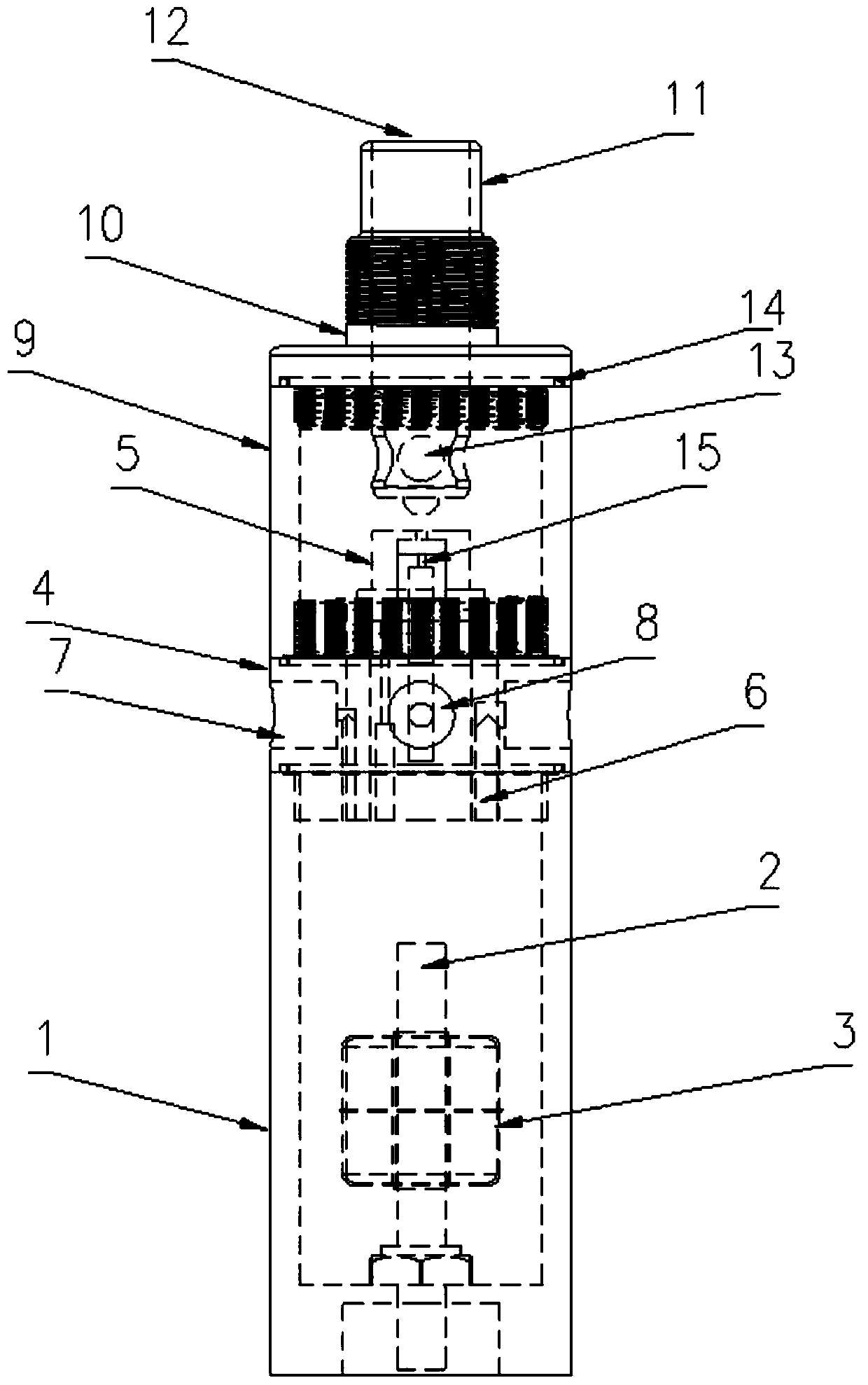
The invention discloses a high-humidity N2 generator, which comprises a water cavity, a gas-liquid confluence device, an atomization cavity and a mist leading-out device. A water inlet pipe is installed in the water cavity, a liquid level sensor is installed on the water inlet pipe and used for giving off an water supplying alarm, when the liquid level in a low position; an atomization cap is arranged at the top of the gas-liquid confluence device, the atomization cap is located in the atomization cavity, a plurality of liquid inlet holes and backflow holes, which are communicated with the water cavity are formed in the bottom of the gas-liquid confluence device, an overflow port and a nitrogen inlet are formed in the side face of the gas-liquid confluence device; the mist leading-out device is provided with a leading-out pipe, a wet nitrogen outlet is formed in the upper end of the leading-out pipe, the lower end of the leading-out pipe extends into the atomization cavity, and a plurality of hole channels communicated with the atomization cavity are formed in the side face of the lower end of the leading-out pipe. The N2 generator is reasonable in design, simple in structure, convenient to operate, capable of providing high-humidity nitrogen, effectively controlling the nitrogen humidity, and meeting the use requirements, high in stability, effectively guarantees the stabilityand durability, is capable of automatically controlling water feeding when water in the water cavity is insufficient, can automatically give an alarm when water overflowing happens, and has a popularization value.

Description

technical field [0001] The invention belongs to the technical field of humidification devices, and in particular relates to a high-humidity N2 generator. Background technique [0002] Chemicals with particles (abrasives) in the microelectronics industry (abrasive fluid, sandblasting fluid, cutting fluid, polishing fluid, etc.), in order to avoid the liquid being thin on the side of the container when the liquid level is settling during use, and because the general prevention of pollution will Nitrogen is used as nitrogen blanket, and nitrogen is generally 99.99% dry; in order to prevent the sedimentation of the liquid surface, particles (abrasives) / grinding abrasive particles are precipitated on the surface of the container, most of these particles are in the range of 10-2000nm, because of the Van DerWarr force Changes in the surrounding potential will cause these dry particles to gather, and when they fall into the liquid surface, large particle deposits will form, which wi...

Claims


Application Information

Patent Timeline
IPC IPC(8): B01F3/04B01F15/02
CPCB01F23/23B01F35/712
Inventor 郑圣弘
Owner 深圳融科科技有限公司
Learn More