Heat source recognition device, unmanned aerial vehicle and heat source recognition method

A recognition device and recognition method technology, applied in three-dimensional position/channel control, vehicle position/route/height control, non-electric variable control, etc., can solve problems such as high false alarm rate, fire false alarm, complex urban environment, etc. Achieve the effect of reducing the high false alarm rate and ensuring accuracy

Active Publication Date: 2020-05-26
PRODRONE TECH (SHENZHEN) CO LTD
View PDF5 Cites 10 Cited by
  • Summary
  • Abstract
  • Description
  • Claims
  • Application Information

AI Technical Summary

Problems solved by technology

[0003] However, the urban environment is complex, and there are high-temperature objects such as chimneys and construction machinery. Therefore, when infrared thermal imaging equipment detects such objects, false alarms will be generated. For this, currently, the method of adjusting the threshold or setting the detection range is mostly used. The way to reduce false alarms, but this kind of treatment will cause the situation of fire omission
Similarly, pyrotechnic recognition through visible light will also be affected by factors such as the complex environment of the city and weather conditions, such as the occlusion of tall buildings and extreme weather conditions, etc. Unable to meet the needs of urban fire alarm

Method used


Image

  • Heat source recognition device, unmanned aerial vehicle and heat source recognition method
  • Heat source recognition device, unmanned aerial vehicle and heat source recognition method
  • Heat source recognition device, unmanned aerial vehicle and heat source recognition method

Examples


Embodiment 1

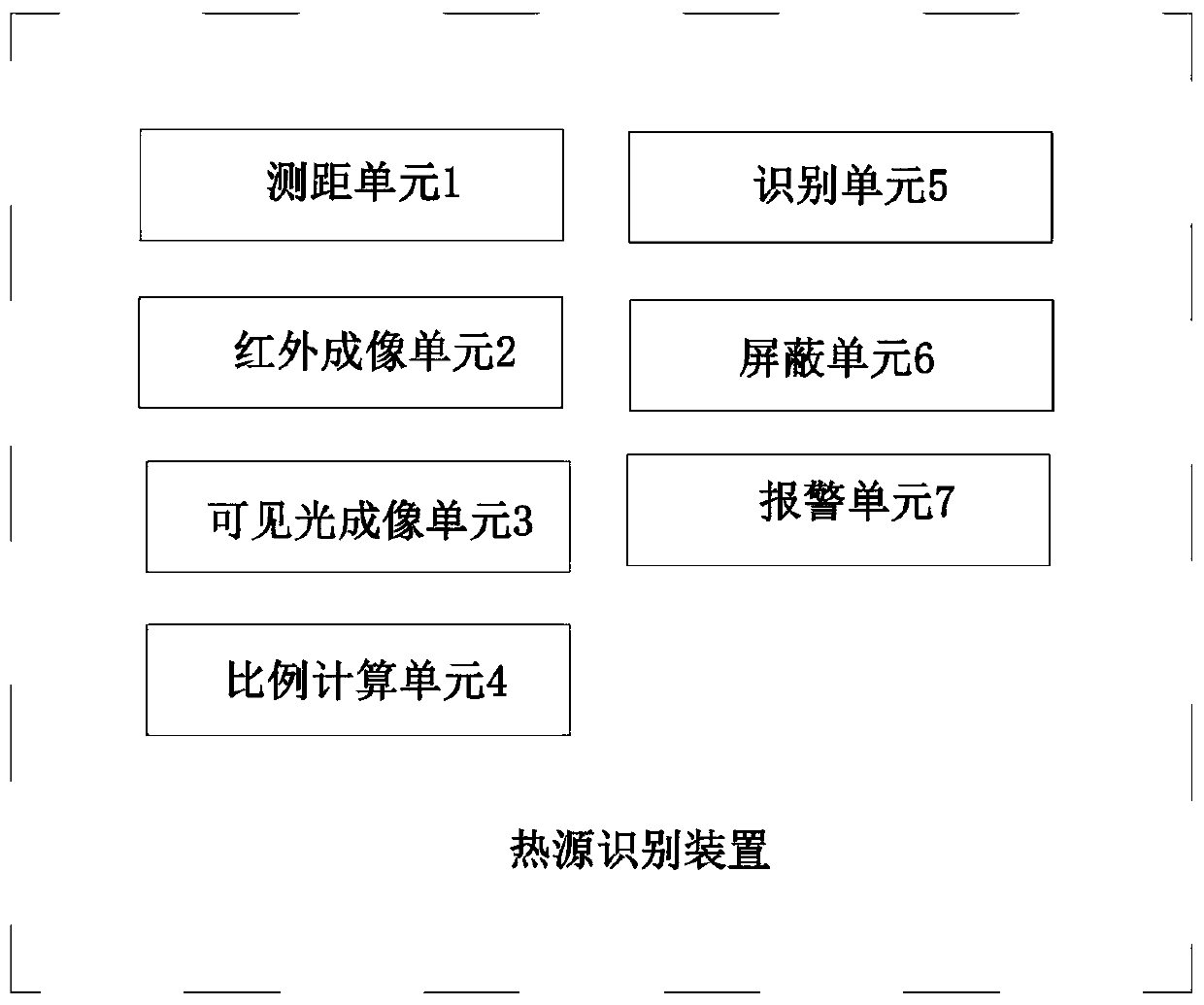
[0031] Such as figure 1 As shown, the heat source identification device in this embodiment includes: a distance measuring unit 1, which is used to obtain the distance information of the heat source, and the distance measuring unit 1 can be a laser range finder; an infrared imaging unit 2 comprising an infrared lens, which It is used to obtain the infrared image of the heat source at the first focal length; the ratio calculation unit 4 is used to calculate the proportion of the heat source in the infrared image to determine the size of the heat source; the visible light including the visible light lens The imaging unit 3 is configured to acquire a visible light image of the heat source at the second focal length according to the size of the heat source and the distance information of the heat source, so that in the visible light image obtained at the second focal length at this time, the The proportion of the heat source is a preset value (preferably, the preset value is 1 / 5-1 / ...

Embodiment 2

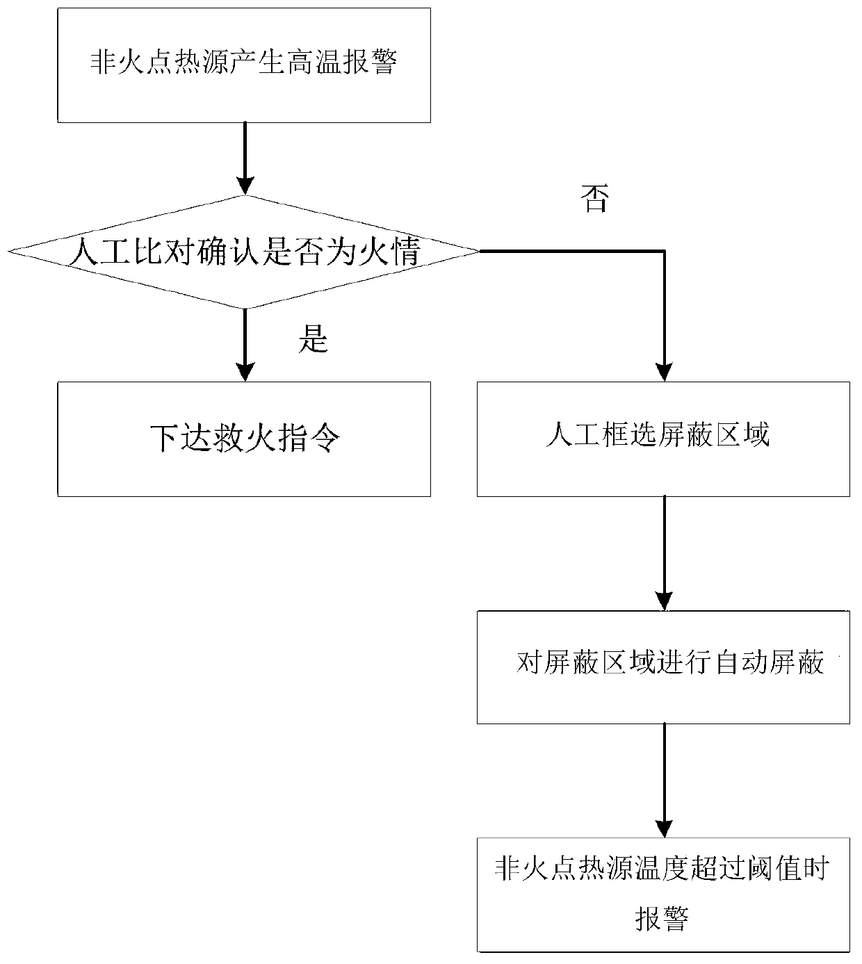
[0038] The difference between this embodiment and Embodiment 1 is that the heat source identification device further includes: a shielding unit 6, which is used to automatically and / or manually shield the non-ignition heat source after judging that the heat source is a non-ignition heat source ;

[0039] And an alarm unit 7, which is used to monitor the temperature change of the non-ignition heat source, and generate an alarm signal when the temperature of the non-ignition heat source exceeds a threshold.

[0040] Therefore, the detection efficiency can be improved by shielding the non-fire point heat source, and false alarms can be further reduced. And when the temperature of the non-ignition heat source exceeds the threshold value, an alarm signal is generated, so as to ensure that the fire can also be alarmed in time when the non-ignition heat source causes a fire, and false alarms are prevented.

[0041] Embodiment two:

[0042] This embodiment provides an unmanned aeria...

Embodiment 3

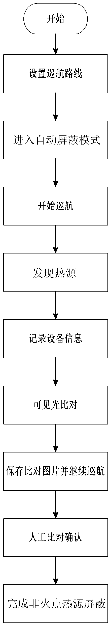
[0044] This embodiment provides a heat source identification method that can be realized by the UAV described in Embodiment 2, such as figure 2 As shown, it includes the following steps:

[0045] S1. Set the monitoring area, such as pre-setting the cruising route of the drone;

[0046]S2. The heat source identification device enters the automatic shielding mode, and the drone starts to cruise; when a heat source is detected in the monitoring area, record the equipment information such as the orientation and pitch of the drone platform at this time; and measure distance by laser Acquire the distance information of the heat source, and obtain the infrared image of the heat source at the first focal length (ie, the focal length of the infrared lens), and calculate the proportion of the heat source in the infrared image to determine the distance of the heat source. size;

[0047] S3. Adjust the focal length of the visible light lens to the second focal length according to the s...


PUM


Abstract

The invention discloses a heat source recognition device, an unmanned aerial vehicle and a heat source recognition method. The device comprises an infrared imaging unit which is used for obtaining aninfrared image of a heat source under a first focal length, a proportion calculation unit which is used for calculating the proportion of the heat source in the infrared image so as to determine the size of the heat source, a visible light imaging unit which is used for acquiring a visible light image of the heat source under a second focal length according to the size of the heat source and the distance information of the heat source, and a recognition unit which is used for judging whether the heat source is a fire point according to the visible light image. The heat source is discovered through infrared imaging, the visible light imaging unit further adjusts the focal length according to the size of the heat source so as to obtain the visible light image, and whether the heat source isa fire point is judged through the visible light image, so that interference of a non-fire-point heat source on infrared detection can be eliminated, and the problems of false alarm rate and high missing report rate are reduced.

Description

technical field [0001] The invention relates to the field of fire engineering, in particular to a heat source identification device, an unmanned aerial vehicle and a heat source identification method. Background technique [0002] At present, the fire point alarm of urban monitoring is mainly realized by uncooled infrared thermal imaging camera for fire point detection, or by visible light for pyrotechnic identification. [0003] However, the urban environment is complex, and there are high-temperature objects such as chimneys and construction machinery. Therefore, when infrared thermal imaging equipment detects such objects, false alarms will be generated. For this, currently, the method of adjusting the threshold or setting the detection range is mostly used. Ways to reduce false alarms, but this kind of treatment will cause fires to miss the situation. Similarly, pyrotechnic recognition through visible light will also be affected by factors such as the complex urban envi...

Claims


Application Information

Patent Timeline
Patent Type & Authority Applications(China)
IPC IPC(8): G08B17/12G05D1/10
CPCG05D1/101G08B17/12
Inventor 黄立邹翔邓俊杰万鹏飞薛源顾兴刘华斌王效杰
Owner PRODRONE TECH (SHENZHEN) CO LTD
Why Eureka
Try Eureka