Hydraulic spool valve

A hydraulic spool valve and valve hole technology, applied in the field of hydraulic spool valves, can solve the problems of increased leakage, no detailed investigation of flow loss, increased wear of the control piston and housing, etc., to achieve the effect of high-quality control edges

Active Publication Date: 2020-05-19
ROBERT BOSCH GMBH
View PDF7 Cites 1 Cited by
  • Summary
  • Abstract
  • Description
  • Claims
  • Application Information

AI Technical Summary

Problems solved by technology

This rotational movement leads to increased wear at the control piston and housing and to increased leakage
In DE 36 44 269 the flow losses caused by the annular flow itself are not considered in detail

Method used


Image

  • Hydraulic spool valve
  • Hydraulic spool valve
  • Hydraulic spool valve

Examples


Embodiment Construction

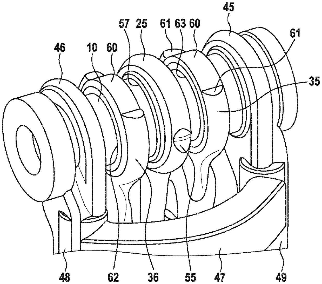
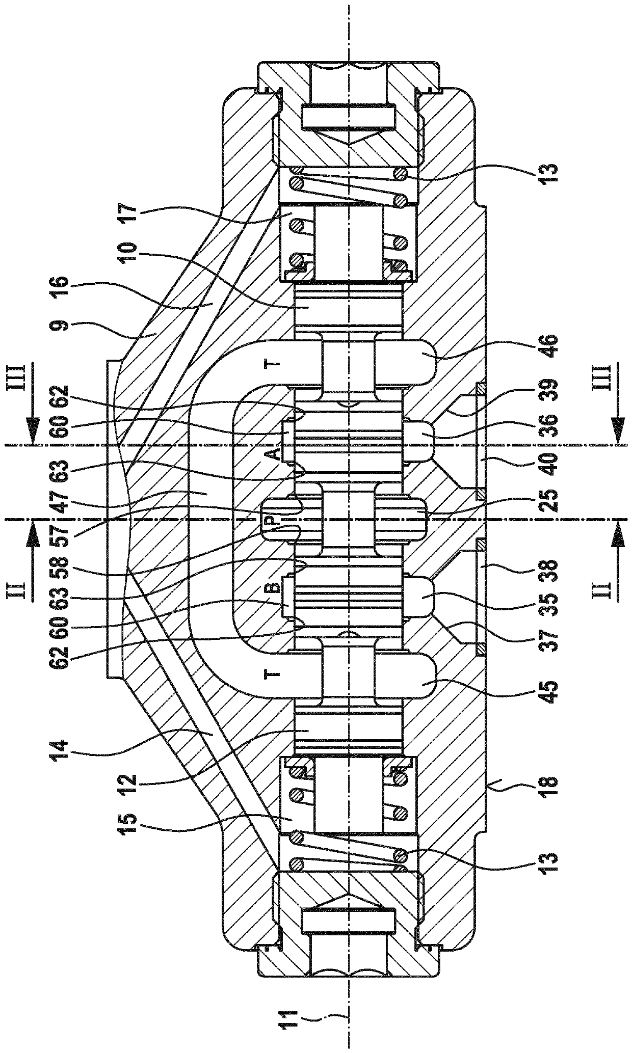
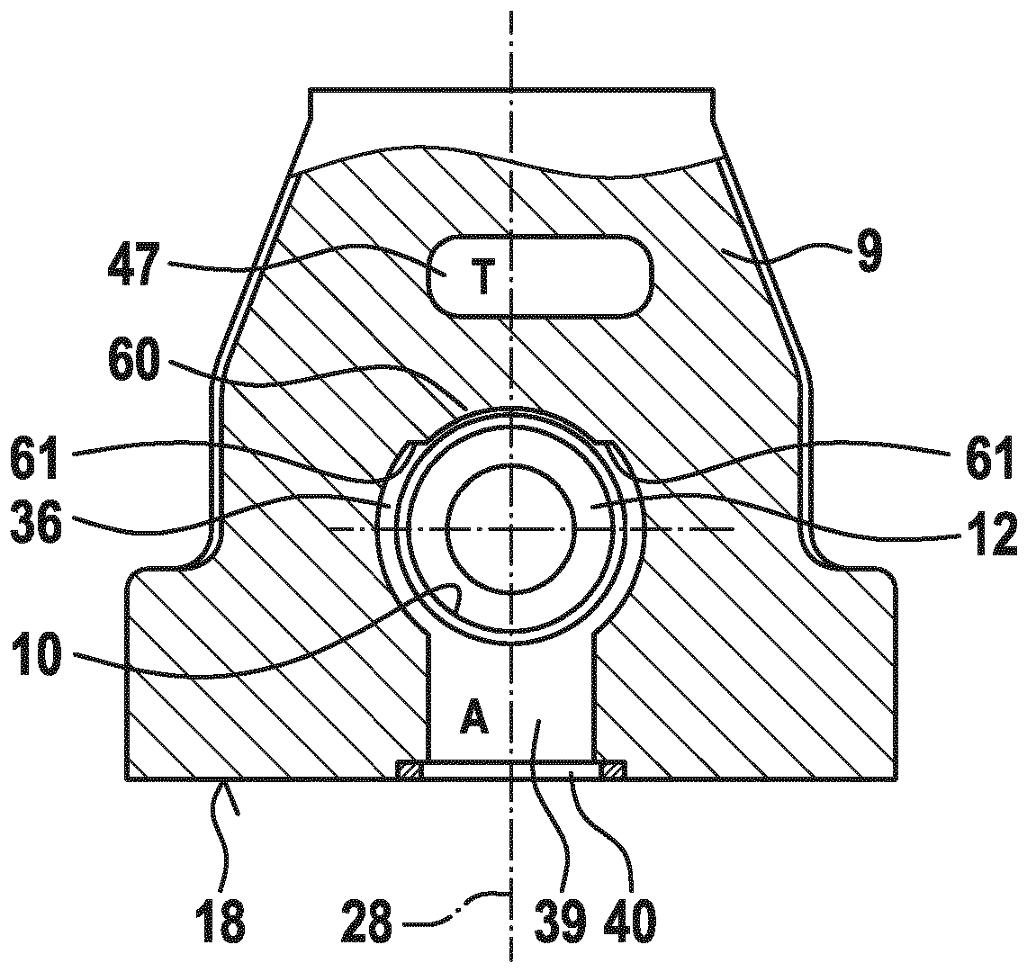
[0056] The hydraulic slide valve shown is a 4 / 3-way valve, ie a directional valve with four ports and three switching positions. The four connections are a pump connection, a tank connection and two load connections to which, for example, a double-acting hydraulic cylinder is connected.

[0057] The spool valve is electrohydraulically pilot controlled. The slide valve has a valve housing 9 , which is penetrated by a valve bore 10 with a center axis 11 , in which a control piston 12 is movable in two opposite directions. The control piston 12 is centered by means of two centering springs 13 in a central position in which all ports are locked relative to each other. A pilot control channel 14 leads from an electromagnetically actuatable pilot valve, not shown, to a first pressure chamber 15 upstream of one end side of the control piston 12 , and a second pilot control channel 16 leads from the pilot valve to a A second pressure chamber 17 upstream of the other end of the contr...


PUM


Abstract

The invention relates to a hydraulic spool valve comprising a valve housing (9) which comprises a valve bore (10) having two control chambers (25), which directly follow one after the other axially ata distance and extend beyond the diameter of the valve bore. The valve housing also has, in a connection surface, a pump connection opening (27), which is connected by means of a first fluid channel(26) to a first of the two control chambers, and a consumer connection opening, which is connected by means of a second fluid channel to a second of the two control chambers. The hydraulic spool valvealso comprises a control piston (12), which is guided so as to be moveable back and forth in the valve bore to fluidically connect the two control chambers with each other and separate said control chambers from each other. A radial web (55) of the valve housing projects into each control chamber, the extension of said web being delimited in the circumferential direction. To particularly effectively avoid annular flows in the control chambers and flow losses associated therewith, the second web in the second control chamber is longer in the circumferential direction than the first web in thefirst control chamber.

Description

technical field [0001] The invention relates to a hydraulic slide valve with a valve housing having a valve bore with two control chambers and a pump connection opening and a load connection opening in a connection surface, and a control piston , the two control chambers are next to each other in an axially spaced manner and beyond the diameter of the valve bore, the pump connection opening is connected to the first of the two control chambers through a first fluid channel, so The load connection opening is connected to the second of the two control chambers via a second fluid channel, and the control piston is guided in a reciprocating manner in the valve bore, so that the two control chambers are fluidly connected to each other and fluidly separated from each other. A radial web of the valve housing protrudes into each control chamber, said web being delimited in the circumferential direction in the extension of the control chamber. Background technique [0002] Such a h...

Claims


Application Information

Patent Timeline
IPC IPC(8): F16K11/07F16K27/04F15B13/04
CPCF16K11/0708F16K27/041F16K11/07F16K31/122
Inventor G.肖佩尔W.策A.克勒佩尔
Owner ROBERT BOSCH GMBH
Why Eureka
Try Eureka