High-speed and high-precision desktop type small near-field tester

A tester, desktop technology, applied in the field of high-speed high-precision desktop small near-field tester, can solve the problems of high noise, backlash, and difficulty in improving the accuracy of transmission components, and achieve high speed, low noise, and fast installation and debugging , save the effect of counterweight equipment

Pending Publication Date: 2020-05-19
CHINA ELECTRONICS TECH GRP CORP NO 14 RES INST
View PDF7 Cites 3 Cited by
  • Summary
  • Abstract
  • Description
  • Claims
  • Application Information

AI Technical Summary

Problems solved by technology

[0004] At present, the transmission form adopted by domestic and foreign near-field testers is mostly the traditional "rotary motor + ball screw or rack and pinion" form. This form requires intermediate transmission links such as reducers and couplings, and there is a backlash , high noise, complex structure and other shortcomings, and the precision of transmission components is difficult to improve due to the influence of manufacturing costs, making the system unable to meet the needs of high precision and high speed
[0005] In addition, small near-field testers at home and abroad are mainly based on an inverted "T" structure, and the near-field tester and the antenna under test are mostly installed independently. The parallelism between the near-field tester and the antenna under test is important. The adjustment index, but limited by the measurement and adjustment equipment, the debugging is complicated, and the accuracy is more difficult to guarantee

Method used


Image

  • High-speed and high-precision desktop type small near-field tester
  • High-speed and high-precision desktop type small near-field tester
  • High-speed and high-precision desktop type small near-field tester

Examples


Embodiment Construction

[0022] In order to enable those skilled in the art to better understand the technical solution of the present application, the present invention will be further described in detail below in conjunction with the accompanying drawings.

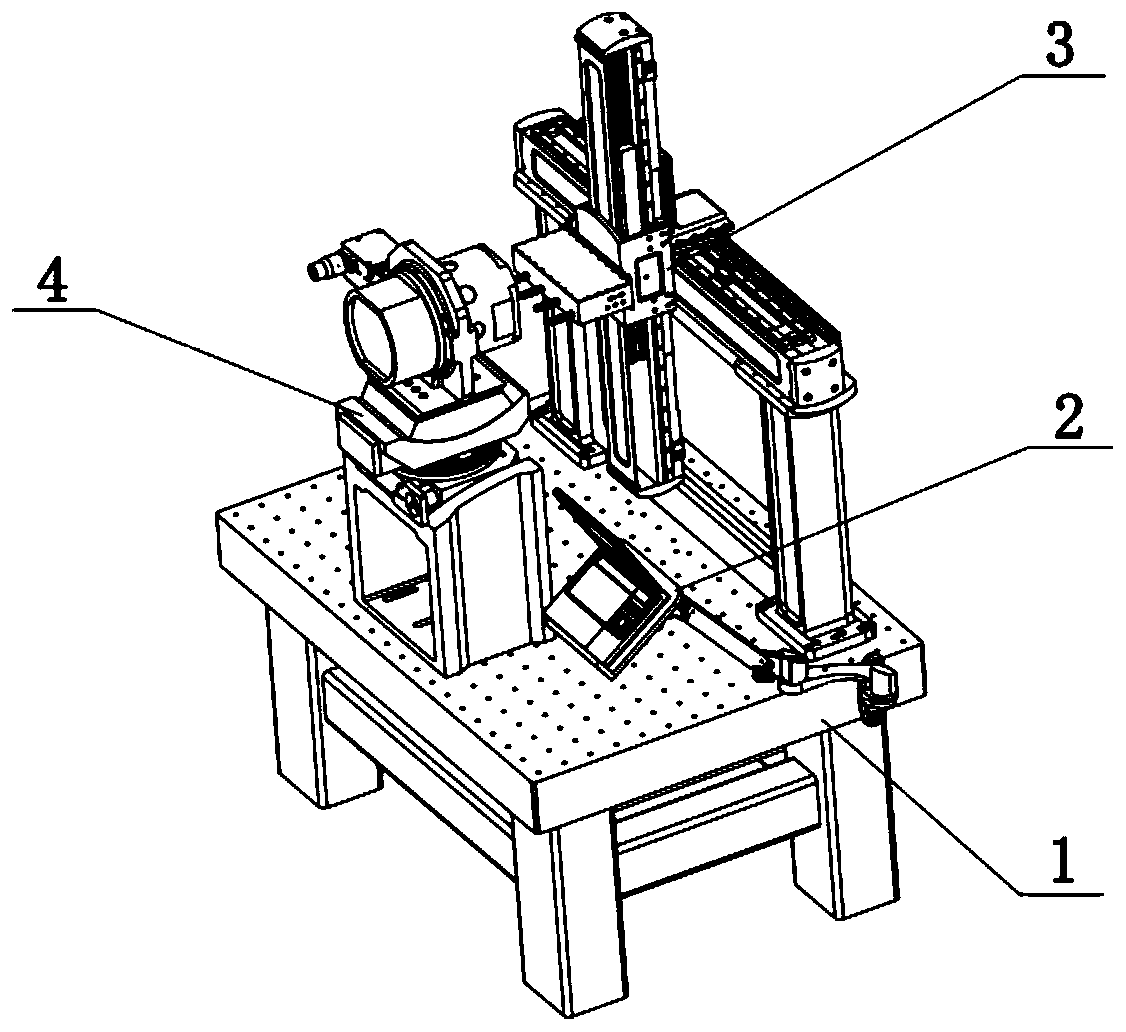
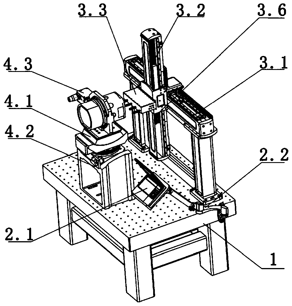
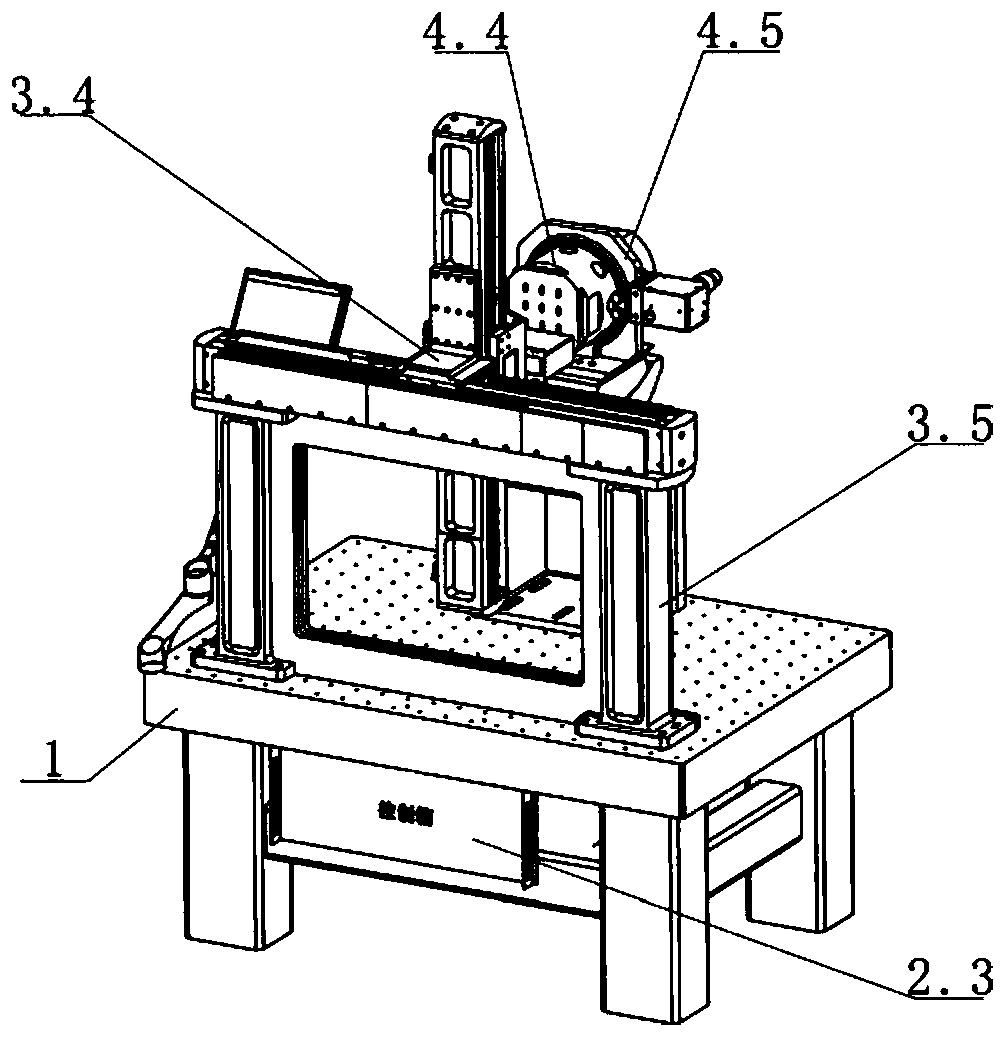
[0023] combined with Figure 1-4 A high-speed and high-precision desktop small-scale near-field tester of the present invention is described in detail. The near-field tester includes a two-dimensional cross scanning mechanism 3 and a test carrying mechanism 4. The test carrying mechanism 4 and the two-dimensional cross scanning mechanism 3 are spaced in parallel before and after Setting, the test bearing mechanism 4 includes a two-dimensional high-precision adjustment turntable 4.1 and an antenna mounting bracket 4.5 arranged on the upper part of the two-dimensional high-precision adjustment turntable 4.1 for installing the antenna 4.4 under test, and the two-dimensional cross scanning mechanism 3 includes a horizontal setting. The base 3.1 and ...


PUM


Abstract

The invention belongs to the technical field of antenna testing. The invention particularly relates to a high-speed and high-precision desktop type small near-field tester which comprises an optical platform, a two-dimensional cross scanning mechanism, a test probe, a control box, a two-dimensional high-precision adjusting turntable, an antenna mounting bracket, a parallelism detector, a control terminal and a terminal adjusting mechanism, the two-dimensional high-precision turntable and a two-dimensional cross mechanism are arranged on the optical platform in parallel front and back at intervals; the antenna mounting bracket is arranged at a rear part of the two-dimensional high-precision adjusting turntable; the test probe and the antenna mounting bracket are oppositely arranged; the test probe can move up and down and left and right for scanning through the two-dimensional cross scanning mechanism; the control terminal is movably connected with the optical platform through the terminal adjusting mechanism, the control terminal is connected with the control box through a circuit or a wireless signal, the control box is connected with a driving element of the two-dimensional crossscanning mechanism through a circuit or a wireless signal, the whole tester system is integrated on the optical platform, and the high-precision and high-speed testing, high repeated positioning precision and low noise are achieved.

Description

technical field [0001] The invention relates to the technical field of antenna testing, in particular to a high-speed and high-precision desktop small near-field tester. Background technique [0002] With the rapid development of aerospace technology, the performance requirements for airborne, missile-borne, and space-borne antennas are getting higher and higher. The measurement of antenna characteristic parameters is an important part of antenna design. There are many methods for antenna characteristic parameter measurement. At present, the main The methods include three categories: antenna far-field measurement, antenna compact field measurement, and antenna near-field measurement. Among them, antenna near-field measurement is mainly divided into: planar near-field, cylindrical near-field and spherical near-field. [0003] There are many error sources that affect the measurement accuracy of the antenna plane near-field, but the most influential error term comes from the ac...

Claims


Application Information

Patent Timeline
Patent Type & Authority Applications(China)
IPC IPC(8): G01R29/10G01B11/27G01B7/02
CPCG01B7/02G01B11/27G01R29/10
Inventor 姜洋袁新江陈诚
Owner CHINA ELECTRONICS TECH GRP CORP NO 14 RES INST
Why Eureka
Try Eureka