Optical image automatic capturing method of composite detection condition

An optical imaging and composite detection technology, applied in the detection field, can solve problems such as inability to obtain defect identification information, time-consuming, and inability to detect holes.

Pending Publication Date: 2020-05-19
FAVITE
View PDF15 Cites 0 Cited by
  • Summary
  • Abstract
  • Description
  • Claims
  • Application Information

AI Technical Summary

Problems solved by technology

[0005] Following the previous paragraph, during the inspection process of printed circuit boards, after using different intensities or different directions of light to irradiate, only the color scale difference performance of the printed circuit board under this light can be obtained, but it cannot be obtained under other optical conditions. Defect identification information that can be displayed
For example, applying reflected light can detect scratches on the printed circuit board, but cannot detect whether it has holes; applying penetrating light can detect holes in the printed circuit board, but cannot detect whether it has scratches mark
[0006] In the same way, the printed circuit board is irradiated with light sources from different directions one after another, and then the images are captured successively. Although the obtained image analysis is sufficient to effectively identify the information of the defect, it takes a lot of time
For example, first apply reflected light to scan and detect scratches on the printed circuit board, then apply transmitted light, and then scan to detect holes in the printed circuit board, which makes the time required for scanning and detection take at least twice as long

Method used


Image

  • Optical image automatic capturing method of composite detection condition
  • Optical image automatic capturing method of composite detection condition
  • Optical image automatic capturing method of composite detection condition

Examples


Embodiment Construction

[0044] In order to make the structural features of the present invention and the achieved effects have a further understanding and recognition, preferred embodiments and detailed descriptions are specially used, which are described as follows:

[0045] According to the prior art, the conventional automatic optical inspection method for the object under test cannot simultaneously capture images under different optical conditions for comparison. Therefore, the present invention proposes an automatic optical image capture method with complex detection conditions to solve the traditional problems to be improved, so as to improve the accuracy and efficiency of detection results, and will be described in detail below.

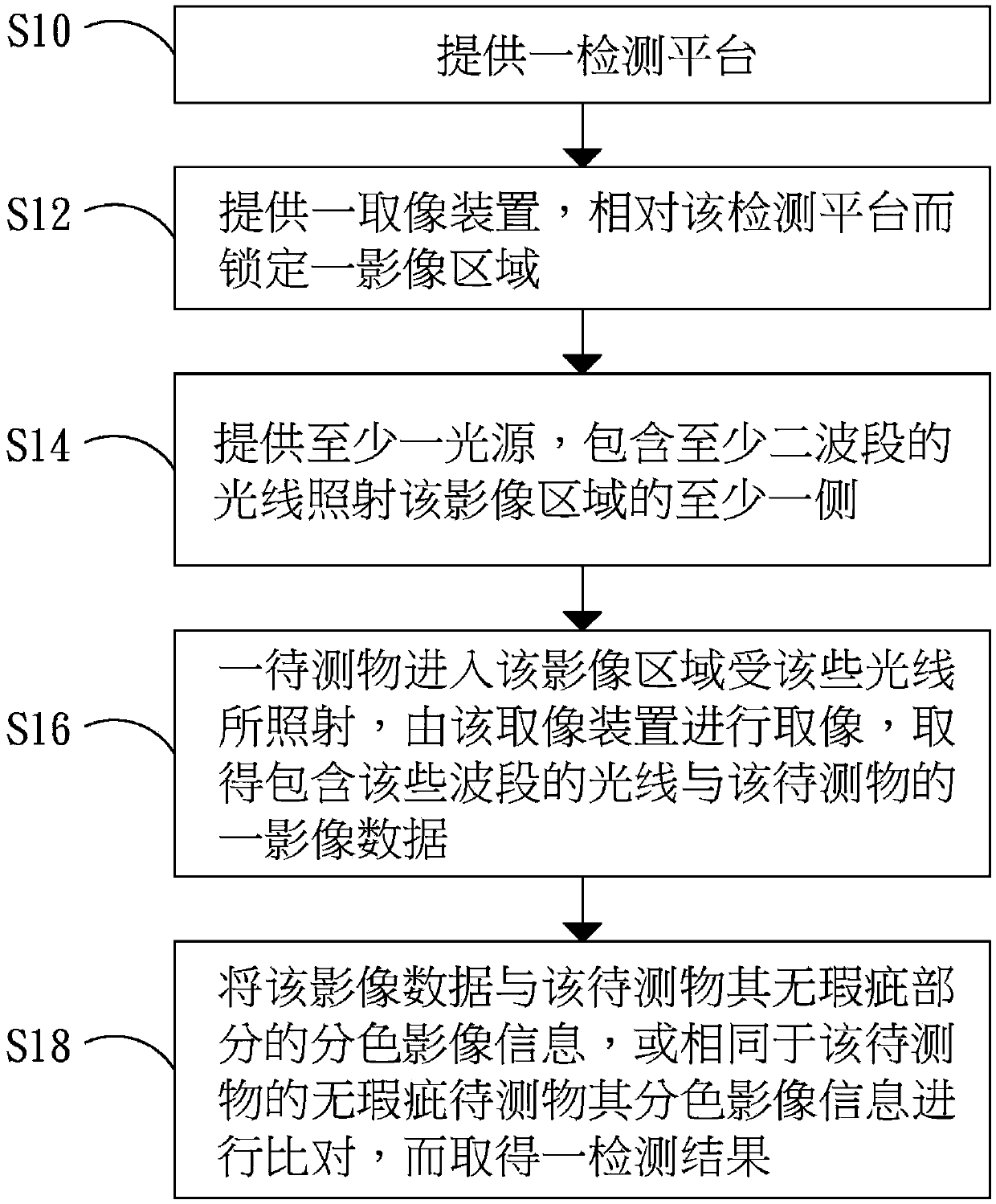
[0046] Here is a description of an optical image automatic capture method with complex detection conditions of the present invention, please refer to figure 1 , which is a flow chart of the method for automatically capturing optical images with complex detection cond...


PUM


Abstract

The invention aims to disclose an optical image automatic capturing method of a composite detection condition. Optical image capturing operation is performed on an object to be detected by using mutual matching of an image capturing device and a light source so as to effectively obtain a detection result of a good / inferior product under irradiation of light rays with different wave bands and further improve detection efficiency.

Description

technical field [0001] The present invention relates to a detection method, in particular to a method for automatically capturing optical images through composite detection conditions. Background technique [0002] The products that are produced online are controlled by manual inspection in the early stage. Due to the limitations of the human eye's visual experience, there will be subjective cognition differences, such as the inability to judge in detail the defects in fast-moving, micron-to-nano-scale fine-sized products, or the special conditions of the external testing environment and the product itself Due to limitations in the visible region of the spectrum, defects in products cannot be accurately visualized by the human eye. Later, the method of manually matching instruments was developed for quality control operations. However, missed inspections often occurred due to the physiological state of the inspectors or improper operation of the instruments. [0003] Today...

Claims


Application Information

Patent Timeline
Patent Type & Authority Applications(China)
IPC IPC(8): G01N21/88
CPCG01N21/8851
Inventor 林传宗
Owner FAVITE
Why Eureka
Try Eureka