
Multi-position wafer edge polishing equipment

A multi-station, edge technology, used in grinding/polishing equipment, metal processing equipment, machine tools suitable for grinding workpiece edges, etc., can solve the problems of high wafer hardness, brittleness, and low yield. Achieve the effect of avoiding excessive impact, reducing stress and improving practicability

Active Publication Date: 2020-05-19
湖南科鑫泰电子有限公司
View PDF11 Cites 1 Cited by
  • Summary
  • Abstract
  • Description
  • Claims
  • Application Information

AI Technical Summary

Problems solved by technology

[0002] The wafer is formed by slicing the whole ingot. With the shrinking of the parts of the electronic device, the application of the wafer on the electronic device is gradually increasing. For the surface granularity, geometric parameters, edge and surface roughness of the wafer, more and more requirements are proposed. Strict requirements require grinding and polishing of the edge of the wafer. When the wafer is fixed under pressure, the hardness is too high and it is easy to become brittle, causing the wafer being polished to be separated from the middle and folded in half, and the polishing yield is low.

Method used


Image

  • Multi-position wafer edge polishing equipment
  • Multi-position wafer edge polishing equipment
  • Multi-position wafer edge polishing equipment

Examples


Embodiment 1

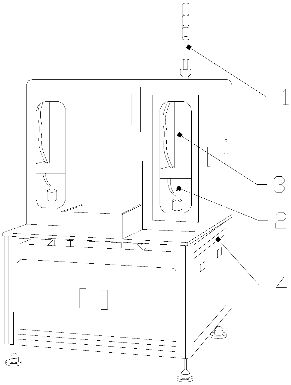
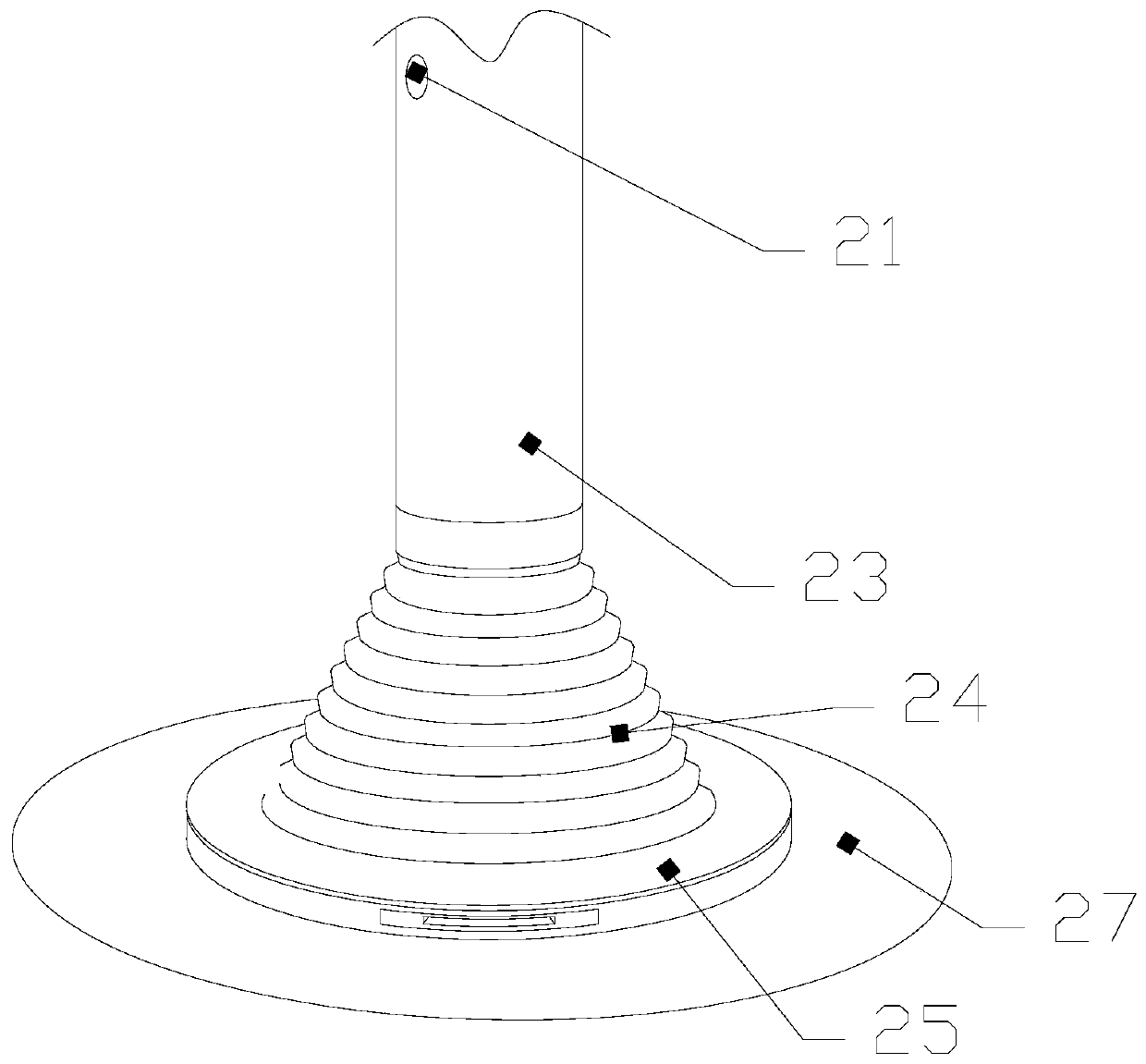
[0030] see Figure 1-Figure 4 , a wafer multi-station edge polishing equipment, the present invention provides a wafer multi-station edge polishing equipment, its structure includes a fixed rod 1, a polishing system 2, a hydraulic cylinder 3, a body 4, the top surface of the body 4 There are two polishing systems 2, and a hydraulic cylinder 3 is arranged directly above the polishing system 2, and the hydraulic cylinder 3 is mechanically connected with the polishing system 2. The top of the body 4 is provided with a fixed rod 1, and the polishing system 2 Including air inlet 21, main rod 23, folding cylinder 24, fixed plate 25, and operating platform 27, the operating platform 27 is fixed directly above the body 4, and a fixed plate 25 is arranged directly above the operating platform 27, and the fixed plate 25 is provided with a folding cylinder 24 on the top surface. The folding cylinder 24 is a hollow structure. The air outlet 21 is mechanically connected with the air inlet...

Embodiment 2

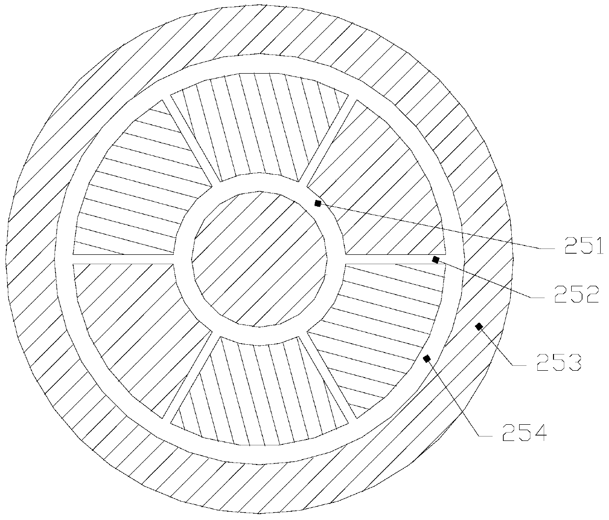
[0035] see Figure 1-Figure 8 , a wafer multi-station edge polishing equipment, the present invention provides a wafer multi-station edge polishing equipment, its structure includes a fixed rod 1, a polishing system 2, a hydraulic cylinder 3, a body 4, the top surface of the body 4 There are two polishing systems 2, and a hydraulic cylinder 3 is provided directly above the polishing system 2, and the hydraulic cylinder 3 is mechanically connected to the polishing system 2, and a fixed rod 1 is provided at the top of the body 4, and the polishing system 2 Including air inlet 21, main rod 23, folding cylinder 24, fixed plate 25, and operating platform 27. The operating platform 27 is fixed directly above the body 4, and a fixed plate 25 is arranged directly above the operating platform 27. The fixed plate 25 is provided with a folding cylinder 24 on the top surface, the folding cylinder 24 is a hollow structure, the folding cylinder 24 is fixedly connected with the fixed plate 2...


PUM


Abstract

The invention discloses multi-position wafer edge polishing equipment. The multi-position wafer edge polishing equipment structurally comprises a fixed rod, two polishing systems, hydraulic cylindersand a machine body. The two polishing systems are arranged on the top end face of the machine body. The hydraulic cylinders are arranged over the corresponding polishing systems. The hydraulic cylinders are in mechanical connection with the corresponding polishing systems. The fixed rod is arranged at the topmost end of the machine body. Each polishing system comprises an air inlet, a main rod, afolding tube, a fixed disk and an operating platform. The operating platforms are fixed to the locations over the machine body. The fixed disks are arranged over the corresponding operating platforms.Through cooperation of the hydraulic cylinders, the main rods and the fixed disks, the multi-position wafer edge polishing equipment fixes wafers through hold-down of the hydraulic cylinders to prevent the wafers from sliding relatively in the fixing process. The multi-position wafer edge polishing equipment adsorbs the wafers in an air extraction mode through cooperation of the fixed disks, theair inlets and the like, sucks and adsorbs the interiors and exteriors of the wafers simultaneously through suction inner rings and suction outer rings to guarantee that adsorption force to the wafersis uniform and the wafers cannot be broken in half from the middles.

Description

technical field [0001] The invention relates to the field of wafer cutting equipment, in particular to a wafer multi-station edge polishing equipment. Background technique [0002] The wafer is formed by slicing the whole ingot. With the shrinking of the parts of the electronic device, the application of the wafer on the electronic device is gradually increasing. For the surface granularity, geometric parameters, edge and surface roughness of the wafer, more and more requirements are proposed. Strict requirements require grinding and polishing of the edge of the wafer. When the wafer is fixed under pressure, the hardness is too high and it is easy to become brittle, causing the wafer being polished to be separated from the middle and split into two halves, resulting in a low polishing yield. Contents of the invention [0003] Aiming at the deficiencies of the prior art, the present invention is realized through the following technical solutions: a multi-station edge polish...

Claims


Application Information

Patent Timeline
Patent Type & Authority Applications(China)
IPC IPC(8): B24B9/06B24B41/00B24B41/02B24B41/06
CPCB24B9/065B24B41/00B24B41/02B24B41/06
Inventor 徐绪友
Owner 湖南科鑫泰电子有限公司
Learn More