Magnetic beverage holder

Inactive Publication Date: 2005-03-17
GARY LONNIE F
View PDF14 Cites 90 Cited by
  • Summary
  • Abstract
  • Description
  • Claims
  • Application Information

AI Technical Summary

Benefits of technology

[0013] The beverage holder of the invention can optionally comprise, in addition to a side wall magnet as described herein, a bottom wall portion in which another magnet is disposed to prevent the beverage holder from sliding along an inclined surface having a major horizontal component. When configured with magnets as disclosed herein disposed in both the bottom and side walls, the user is provided with the option of selectively placing the subject beverage holder on either a substantially vertical or substantially horizontal ferrous metal surface without risk of tipping, rolling or sliding, and associated spillage.
[0014] The magnet used in the side wall section of the subject beverage holder is desirably a permanent magnet and will preferably impart to a substantially vertical wall comprising a major ferrous metal component a magnetic attractive force that is sufficiently large and is applied over a sufficiently large area that the weight of a full beverage container disposed inside the holder is supported in an upright position against the wall without relative motion between the beverage holder and the wall, and without attendant risk of resultant tipping or spillage absent the intervention of another external force. If desired, the subject beverage holder can be made with a separate liner that is made of a polymeric material more rigid than the outer body.

Problems solved by technology

The use of magnets in beverage holders as disclosed in the prior art does not, however, function satisfactorily for the purpose of firmly supporting a full can or bottle of beverage in an upright orientation on a substantially vertical, ferrous metal support surface, such as the side of a motor vehicle, steel beam, wall, filing cabinet, or the like.
The use of a ring magnet or a plurality of magnets disposed around the periphery of the side wall of a cylindrical beverage holder has been found to provide insufficient contact with a substantially planar and vertical support surface to hold a beverage firmly in one position.

Method used


Image

  • Magnetic beverage holder
  • Magnetic beverage holder
  • Magnetic beverage holder

Examples


Embodiment Construction

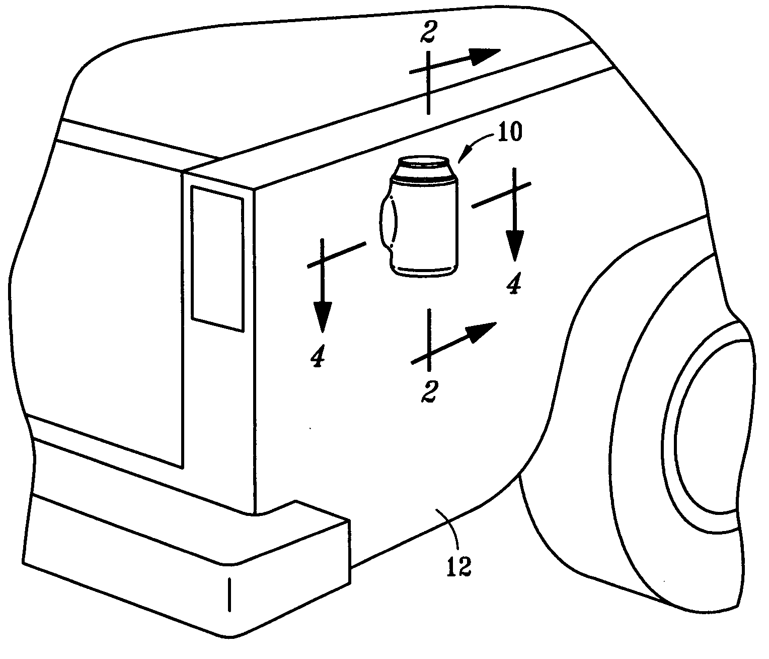
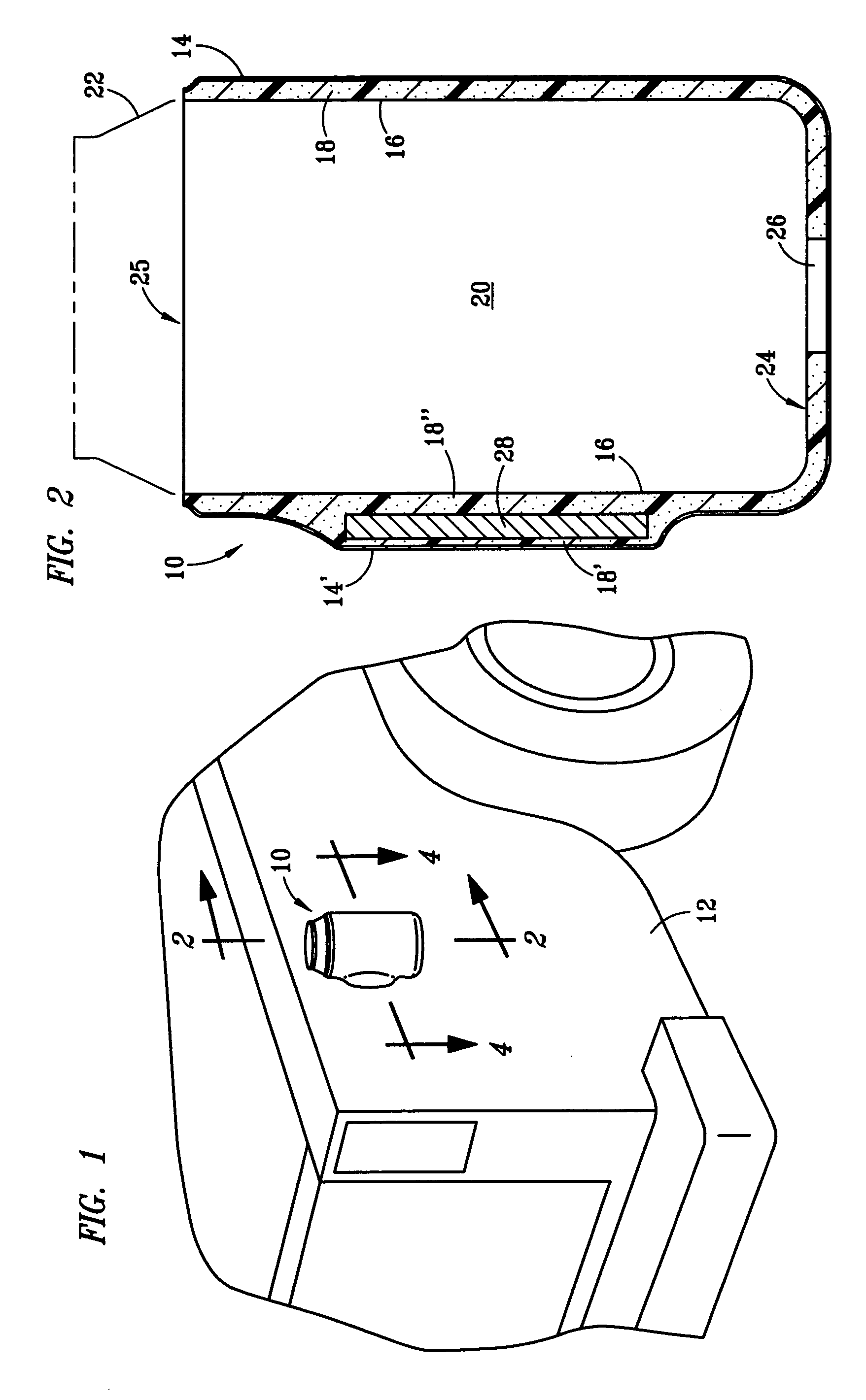
[0029] Referring to FIG. 1, beverage holder 10 of the invention is shown in juxtaposition to a substantially vertical, rear quarter panel 12 of a conventional pickup truck to which beverage holder 10 is releasably attached. At least the portion of quarter panel 12 to which beverage holder 10 is releasably attached is understood to comprise a ferrous metal that is capable of being attracted to the magnetic field of a magnet disposed inside the side wall of beverage holder 10. The magnitude of the attractive force between quarter panel 12 and the magnet disposed inside the side wall of beverage holder 10, when coupled with the normal frictional force present at the interface between quarter panel 12 and the adjacent outside surface of beverage holder 10, is desirably sufficient to resist the gravitational force exerted on beverage holder 10 and hold beverage holder 10 in a desired, substantially upright position relative to quarter panel 12, even when a full beverage container is pres...


PUM


Abstract

A thermally insulative, polymeric beverage holder having inner and outer side wall sections with a magnet having a substantially flat, outwardly facing surface disposed between inner and outer side wall sections of the holder, the magnet imparting to the holder a substantially planar side wall surface that is attachable to a substantially vertical ferrous metal surface with sufficient attractive force to support the weight of a full beverage container disposed inside the holder. A beverage holder having magnets disposed in both the side and bottom walls is also disclosed. Optionally, the beverage holder can include a molded polymeric liner.

Description

BACKGROUND OF THE INVENTION [0001] 1. Field of the Invention [0002] This invention relates to a single beverage holder of the type commonly used for holding and keeping a canned or bottled beverage cool during consumption. Such holders, often referred to as “coozies,” are typically made, at least in part, of a thermally insulative polymeric material. [0003] 2. Description of Related Art [0004] Polymeric beverage holders useful with single cans or bottles are well known. Ordinarily, such beverage holders are made with a side wall that is substantially cylindrical and a bottom that is unitarily formed or separately made. If separately made, the bottom is circumferentially attached to the lower end of the side wall using an adhesive, by sonic welding, or by other similarly effective means. Alternatively, the side walls of conventional beverage holders are sometimes made so that at least the outwardly facing surface is curvilinear in both the vertical and circumferential directions to p...

Claims


Application Information

Patent Timeline
IPC IPC(8): A47G19/22A47G23/02B65D25/22B65D25/24B65D81/38
CPCA47G19/2261A47G23/0225A47G2200/106B65D2313/04B65D25/24B65D81/3881B65D25/22
Inventor GARY, LONNIE F.
Owner GARY LONNIE F
Why Eureka
Try Eureka