
Power cord winding and releasing device

Inactive Publication Date: 2005-05-12
CHANG KUANG PO
View PDF4 Cites 24 Cited by
  • Summary
  • Abstract
  • Description
  • Claims
  • Application Information

AI Technical Summary

Benefits of technology

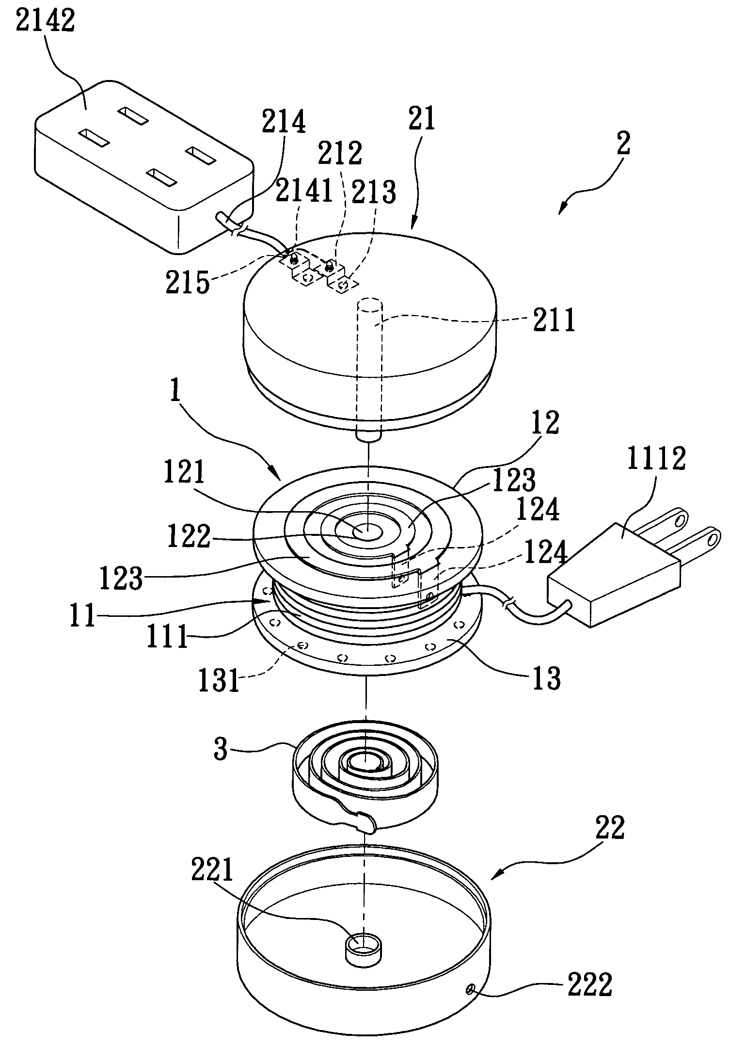
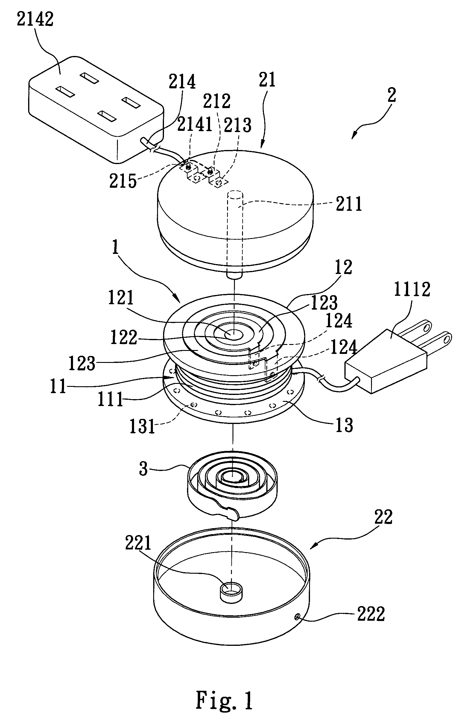
[0004] A primary object of the present invention is to provide a power cord winding and releasing device that enables a power cord to be quickly and orderly received therein for convenient storage or use. To achieve the above and other objects, the device mainly includes a reel around which a first power cord is wound, a housing formed from upper and lower covers for rotatably receiving the reel therein, and a coiled spring strip fixed in a tubular body of the reel to enable an automatic rewinding of the outward pulled first power cord around the reel. An upper surface of the reel is a conductive disc to electrically contact with two conductive plates provided on an inner side of the upper cover. The housing is provided at two sides with two through holes, via which the first and a second power cord separately connected to the conductive disc and the conductive plates are extended out of the housing. The first and the second power cord are connected at their respective outer end with, for example, a plug and a receptacle. The first power cord may be quickly pulled outward and rewound around the reel in the housing in an orderly state.

Problems solved by technology

These power cords tend to become disordered and tangled, and occupy a large space when they are long and large in number.
After the electric or electronic appliance has been relocated in place, the extra length of the extension cord must be troublesomely wound and tied again.
Moreover, a long extension cord that is not in use and arbitrarily wound and tied into a big and loose body is not convenient for storage.

Method used


Image

  • Power cord winding and releasing device
  • Power cord winding and releasing device
  • Power cord winding and releasing device

Examples


first embodiment

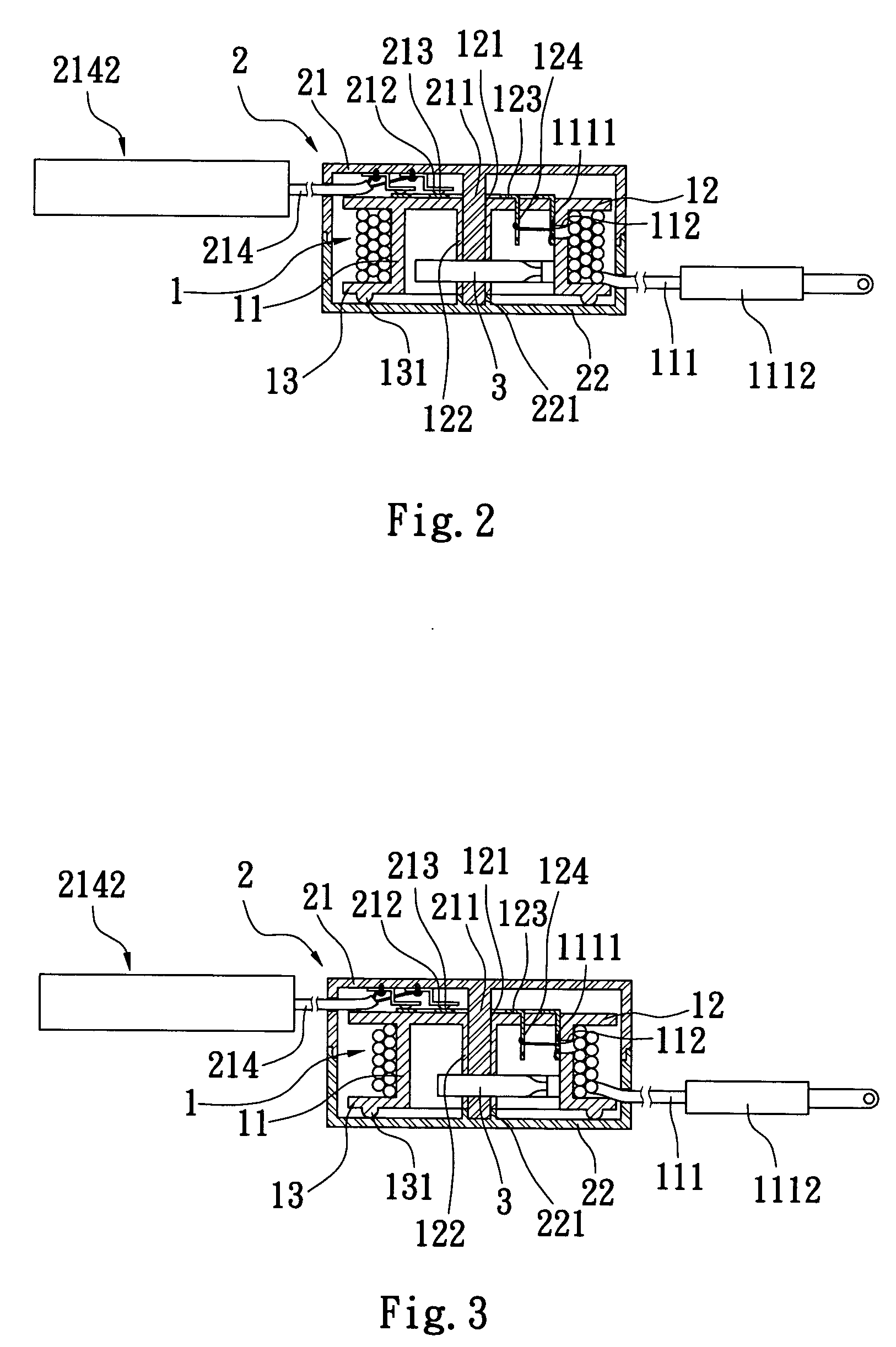
[0012] Please refer to FIGS. 1 and 2 that are exploded perspective and sectioned side views, respectively, of a power cord winding and releasing device according to the present invention. As shown, the power cord winding and releasing device mainly includes a reel 1, a housing 2 for receiving the reel 1 therein, and a coiled spring strip 3 mounted in the reel 1.

[0013] The reel 1 includes a diameter-reduced round tubular body 11 defining an inner space therein, an upper end formed into a diameter-increased conductive disc, and an open lower end having a radially outward extended flange 13.

[0014] The tubular body 11 is provided at one side with a first through hole 112 (see FIG. 2), via which an inner end 1111 of a first power cord 111 is inserted into the tubular body 11 to locate in place. Other portions of the first power cord 111 outside the first through hole 112 are wound around an outer surface of the diameter-reduced tubular body 11. A plug 1112 is connected to an outer end o...

second embodiment

[0023] Please also refer to FIG. 5 that is a sectioned side view of the power cord winding and releasing device according to the present invention in an assembled state. As shown, the catch element 225 includes a bevel angle adapted to engage with the ratchet wheel 125, an upper bar 2251 vertically extended from an upper side of the catch element 225 into the recess 216 on the upper cover 21 via the through hole 218 to connect to the push button 217, and a lower bar 2252 vertically extended from a lower side of the catch element 225 into an upper end the spring 224.

[0024] When the push button 217 is in a normal state without being depressed, as shown in FIG. 5, the push button 217 is upward pushed by the spring 224 to project from the top of the upper cover 22, and the bevel angle of the catch element 225 and the ratchet wheel 125 are in the same one plane. When the plug 1112 is pulled outward and the reel 1 inside the housing 2 is brought to rotate, the ratchet wheel 125, which is ...


PUM


Abstract

A power cord winding and releasing device includes a reel around which a first power cord is wound, a housing formed from upper and lower covers for rotatably receiving the reel therein, and a coiled spring strip fixed in a tubular body of the reel. An upper surface of the reel is a conductive disc to electrically contact with two conductive plates provided on an inner side of the upper cover. The housing is provided at two sides with two through holes, via which the first and a second power cord separately connected to the conductive disc and the conductive plates are extended out of the housing. The first and the second power cord are connected at their respective outer end with a plug and a receptacle. The first power cord may be quickly pulled outward and rewound around the reel in the housing in an orderly state.

Description

FIELD OF THE INVENTION [0001] The present invention relates to a device for orderly storing a power cord or an extension cord, and more particularly to a simple power cord winding and releasing device that enables a power cord to be quickly and orderly received therein for convenient storage. BACKGROUND OF THE INVENTION [0002] With the highly advanced technologies, more and more electric and electronic appliances have been developed and widely used in people's daily life. All these electric and electronic appliances require power cords to obtain required power supply and send electric signals. These power cords tend to become disordered and tangled, and occupy a large space when they are long and large in number. On the other hand, it is possible an electric or electronic appliance is located far away from a power receptacle and requires an extension cord to obtain the power supply. Most currently available extension cords are produced to different standardized lengths. Most users w...

Claims


Application Information

Patent Timeline
IPC IPC(8): H02G11/02
CPCH02G11/02B65H2701/34B65H75/4431
Inventor CHANG, KUANG PO
Owner CHANG KUANG PO
Learn More