Caster system equipped with hand-operated brakes

Active Publication Date: 2012-12-13
HINOMOTO JOMAE
View PDF6 Cites 25 Cited by
  • Summary
  • Abstract
  • Description
  • Claims
  • Application Information

AI Technical Summary

Benefits of technology

[0010]As constituted above, the caster with hand-operated brakes can be made small-sized, light-weighted and low-cost. And also, it is convenient to use as the plural caster-wheels can be locked with single operation.

Problems solved by technology

If such a hand brake for carts is simply applied to a bag caster, that hand brake becomes inconvenient to carry the bag.

Method used


Image

  • Caster system equipped with hand-operated brakes
  • Caster system equipped with hand-operated brakes
  • Caster system equipped with hand-operated brakes

Examples


Embodiment Construction

[0020]Hereinafter, referring to FIGS. 1 to 9, the best mode for carrying out the present invention will be explained in detail.

Description of Embodiments

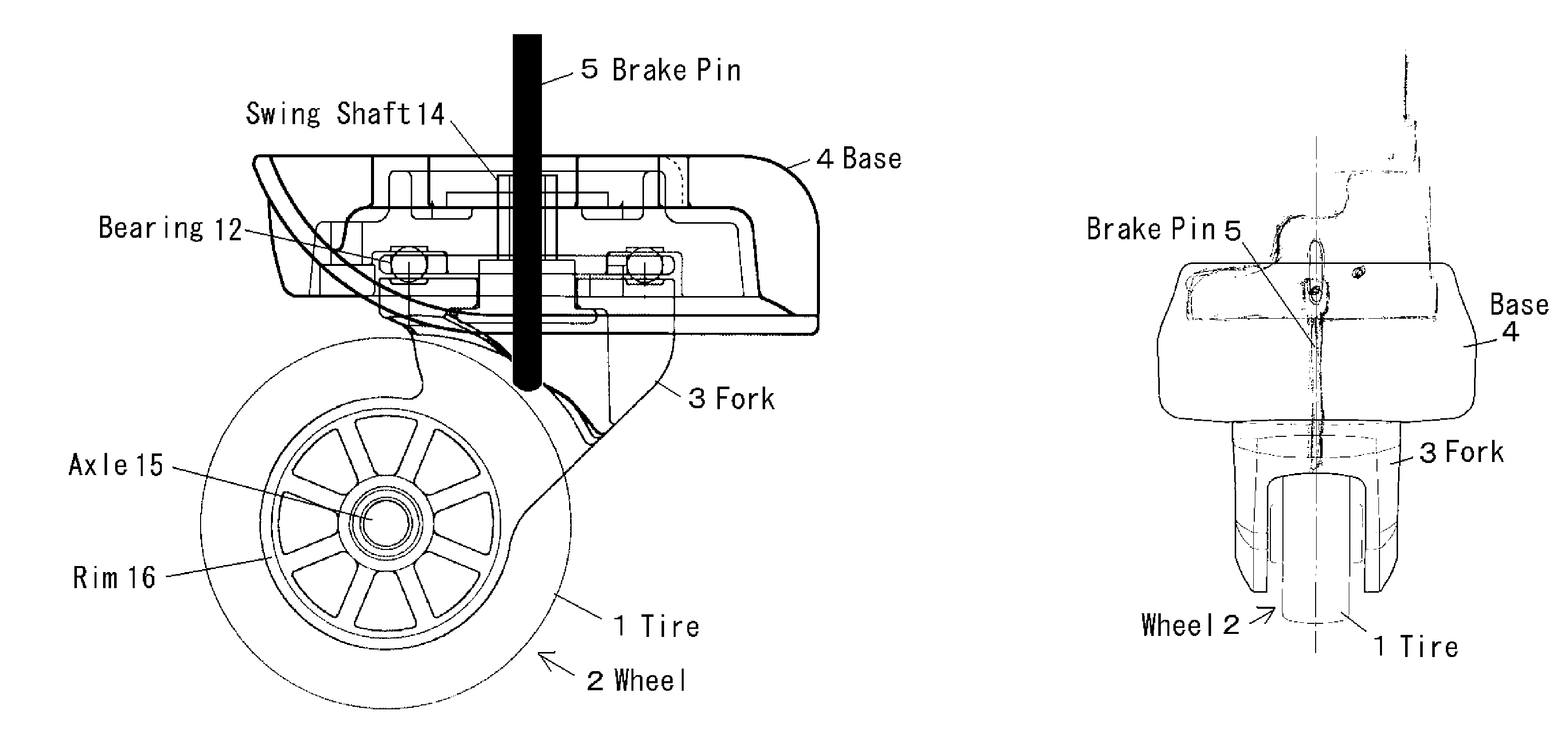
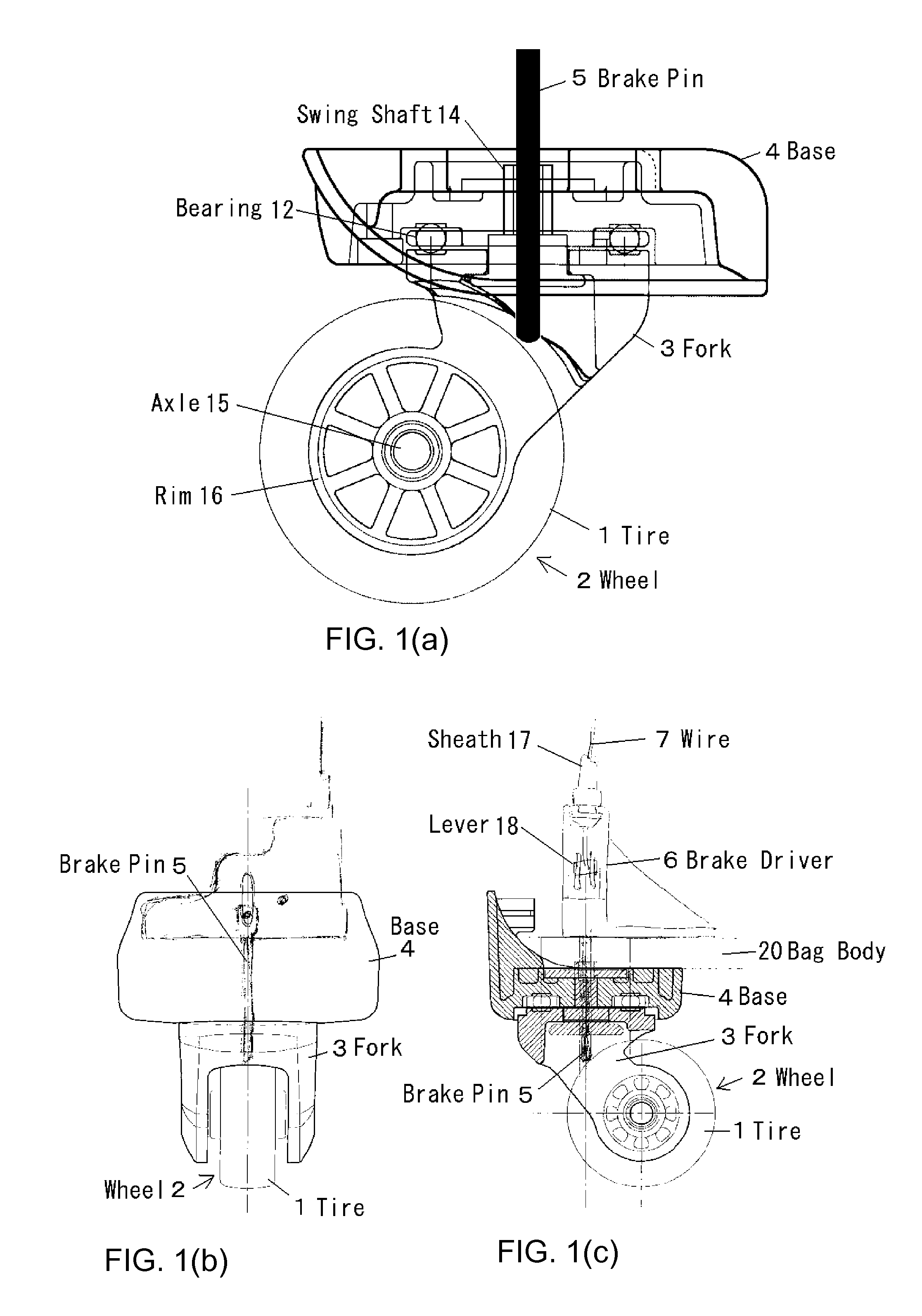
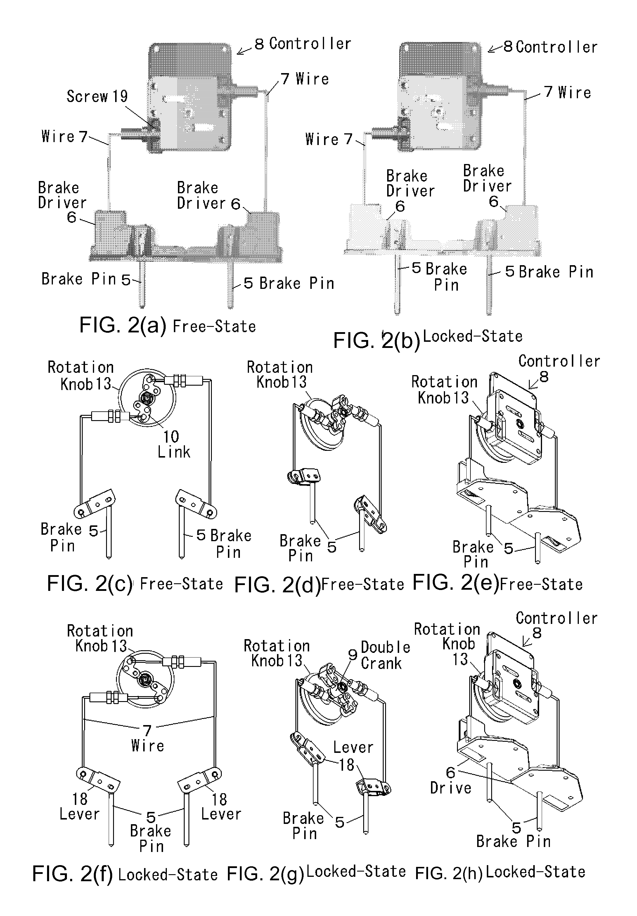
[0021]The embodiment of this invention is a caster with hand-operated brakes wherein the rotation knob of the controller apart from the wheels pulls the connection wire, the force is transmitted via the lever above the wheel to the brake pin that is running in the swing shaft of the fork and the brake pin is pushed to the tire for stopping the rotation of the wheel.

[0022]FIG. 1 shows the wheel structure of the caster with hand-operated brakes. FIG. 2 shows the brake system structure. FIGS. 3 to 5 show the controller structure. FIGS. 6 and 7 show the structure of the brake driver. FIG. 8 shows the operation procedure by the rotation knob. FIG. 9 shows the operation procedure by the handle. In FIGS. 1 to 9, the tire 1 is the rotating tread member made of rubber etc. The wheel 2 is a rotating member made of rim of plastics etc covered ...


PUM


Abstract

Hand-operated brakes caster system is easy to use, compact, lightweight, low-cost. A fork supports a rotating wheel via an axle. A bag mounted base supports the swinging fork. A hollow swing shaft mounts on a base bearing. A force transmitting wire is pulled by a rotation knob in a controller away from the wheel. Opening direction force is applied by a spring to the wire in the opening direction. Therefore, if the knob is rotated by an angle not smaller than a predetermined value, reverse rotational moment is applied, locking the rotation knob. Force transmitted to a lever via the wire is magnified by the action of the lever, and the resulting force pushes a brake pin located inside the fork swing shaft. The brake pin abuts the tire resulting in frictional resistance preventing rotation of the wheel.

Description

TECHNICAL FIELD[0001]The present invention relates to a caster system equipped with hand-operated brakes for bags, especially to the caster system equipped with hand-operated brakes whose wheels can be locked through a controller within reach.BACKGROUND ART[0002]Conventionally, various casters with hand brakes for bags have been developed. Same as the casters for the luggage carts, there are several types of casters with brakes for bags. One example is a wire-type brake in which a wire is pulled for applying brake. Another example is a rod-link type brake in which a rod is pushed or pulled for applying brake via a link. If such a hand brake for carts is simply applied to a bag caster, that hand brake becomes inconvenient to carry the bag. Therefore, there are various elaborations for embedding the hand brake inside the bag. Some examples of the conventional technology relevant to the above-mentioned caster brakes are shown below.[0003]The lock mechanism of a caster described in the ...

Claims


Application Information

Patent Timeline
IPC IPC(8): B60B33/00
CPCA45C5/145Y10T16/195B60B33/0028B60B33/0039B60B33/0049B60B33/0057B60B33/0068B60B33/0073B60B33/0081B60B33/0086B60B33/0092B60B33/021B62B2301/0467B60B2900/111B60B2900/112B60B2900/115B60B33/0023
Inventor EGUCHI, TAMAKI
Owner HINOMOTO JOMAE
Why Eureka
Try Eureka