Eureka AIR delivers breakthrough ideas for toughest innovation challenges, trusted by R&D personnel around the world.

Construction waste treatment device

A processing device, construction waste technology, applied in grain processing, mixer with rotating stirring device, transportation and packaging, etc., can solve problems such as inability to save resources, inability of crushing device to separate concrete and scrap metal, damage to crushing device, etc. Achieve low cost, meet social market demand, and save resources

Active Publication Date: 2020-05-19
ZHENGZHOU UNIV OF IND TECH
View PDF12 Cites 6 Cited by
  • Summary
  • Abstract
  • Description
  • Claims
  • Application Information

AI Technical Summary

Problems solved by technology

[0009] In view of the above situation, in order to overcome the defects of the prior art, the present invention provides a construction waste processing device, which effectively solves the problems that the existing crushing device cannot separate concrete and scrap metal, the scrap metal causes damage to the crushing device, and cannot save resources.

Method used


Image

  • Construction waste treatment device
  • Construction waste treatment device
  • Construction waste treatment device

Examples


Embodiment 1

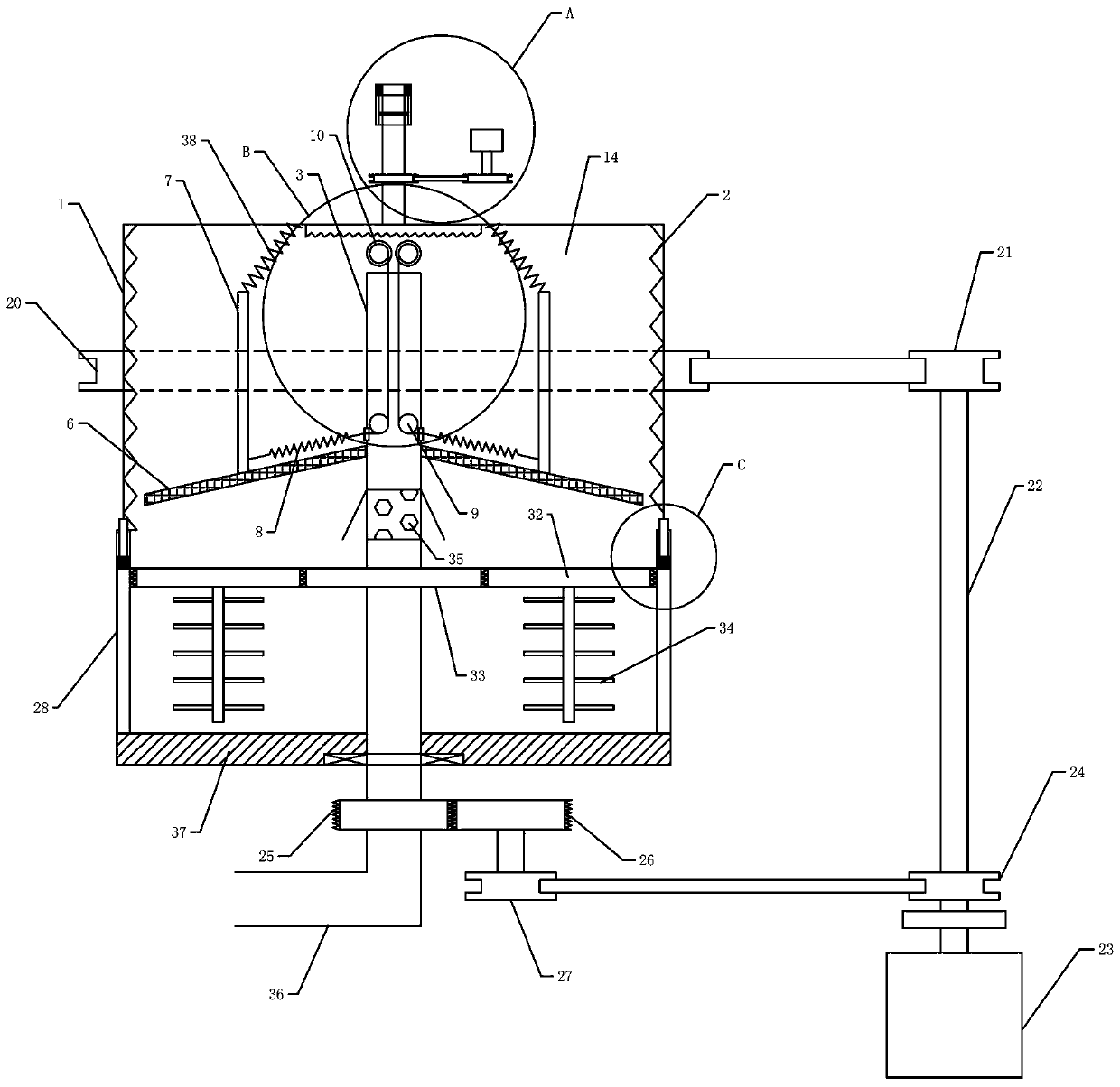
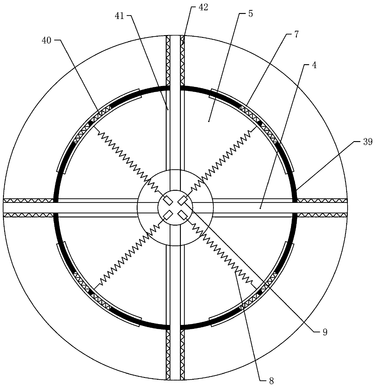
[0040] Embodiment 1. A construction waste treatment device, comprising an upper tank body 1, the upper end of which is a cavity inside the upper tank body 1, and a sawtooth-2 is provided on the inner side wall of the upper tank body 1, for crushing construction waste , the center of the upper tank body 1 is rotatably connected with a through-pipe 3, the inside of the through-pipe 3 is an opening at the upper end of the cavity, and the outer wall of the through-pipe 3 is fixed with a plurality of baffles 4 that are uniformly distributed around the through-pipe 3 around the circumference. The number of plates 4 is 4 or 6, and a crushing bin 5 is formed between a plurality of baffle plates 4, and an inclined filter screen 6 is fixed in the crushing bin 5, and the gap between the filter screen 6 and the sawtooth-2 is 3 cm, and the filter screen 6 From the through pipe 3 to the direction of the outer wall of the tank body 1, the edge of the filter screen 6 is provided with a slidewa...

Embodiment 2

[0046] Embodiment 2, a lower tank body 28 is also provided below the upper tank body 1, and the upper end of the outer wall of the lower tank body 28 is provided with a draw-in groove 29, and an electromagnet 30 is embedded in the bottom of the draw-in groove 29, and the outer side of the upper tank body 1 The wall is rotated and installed in the draw-in groove 29. There are some internal teeth 31 at the upper end of the inner side wall of the lower tank body 28. The internal teeth 31 are meshed with a plurality of gears 3 32, and the gears 3 32 are meshed with gears 4 sleeved on the through pipe 3. 33, the lower end of the gear three 32 is equipped with a stirring shaft 34, and a water inlet 35 is provided on the through pipe 3 in the lower tank body 28, and a baffle plate inclined downward is installed at the water inlet 35, and the through pipe in the upper tank body 1 The through pipe 3 in the pipe 3 and the lower tank body 28 is not connected, and the middle is separated b...

Embodiment 3

[0049] Embodiment 3. The push plate 7 is connected to the upper end of the tank body 1 through a soft shielding curtain 38 to ensure that it can enter the crushing bin 5 when feeding. The two ends of the push plate 7 are stretchable stretch plates 39, Because the separated crushing bin 5 changes in an arc shape, the two ends of the push plate 7 are stretchable stretch plates 39, and the inboard of the stretch plate 39 is connected by a spring 2 40, and the push plate 7 needs to be stretched during the movement. Both sides of filter screen 6 are provided with slideways 41 for it, and the end of stretch plate 39 is connected with its outer side by spring three 42, while the pulley two 10 is wound with coil spring 43, which can well increase the return of push plate 7 force.

[0050] Specific usage method:

[0051] In order to better help the waste building to enter the crushing bin 5, the upper end of the push plate 7 and the upper tank body 1 is connected through a soft shield...


PUM


Abstract

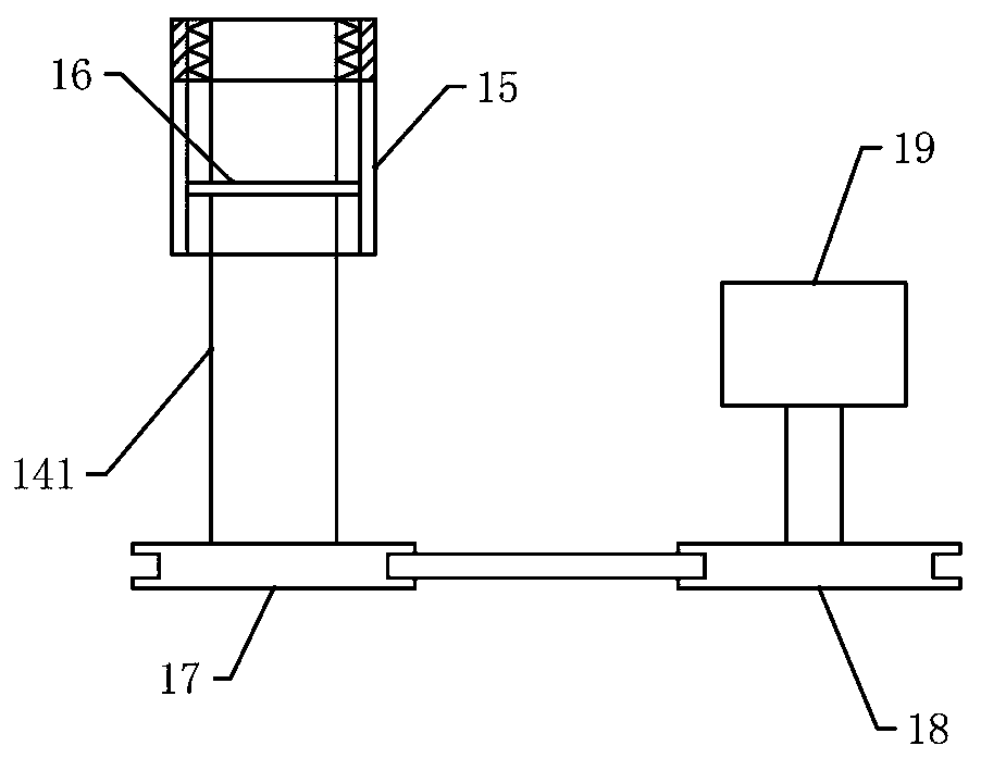
The invention provides a construction waste treatment device. The construction waste treatment device effectively solves the problem that waste metal causes damage to an existing crushing device due to the fact that the crushing device cannot separate concrete and the waste metal. The construction waste treatment device includes an upper tank body, wherein first saw teeth are arranged on the innerside wall of the upper tank body, the center of the upper tank body is rotatably connected with a through pipe, the outer side wall of the through pipe is fixedly connected with a baffle, filter screens are fixed in a crushing bin, the filter screens are slidably connected with push plates, the push plates are connected with first springs, first pulleys are fixed in the through pipe, second pulleys arranged at the upper end of the through pipe are arranged at the upper ends of first pulleys, the second pulleys are coaxially connected with a one-way wheel, helical gears are arranged outside the one-way wheel, the upper parts of the helical gears can be meshed with disc helical teeth, a feeding port placed in the crushing bin is located beside a disc gear, a fixed rod is fixed to the upperend of the disc gear, a cylinder fixedly sleeves the upper end of the fixed rod, and the upper end of the cylinder is connected with the fixed rod in a threaded mode. According to the construction waste treatment device, common crushing requirements can be met, the practicability is high, functions are diversified, and the social market needs can be met.

Description

technical field [0001] The invention relates to the technical field of construction waste, in particular to a construction waste processing device. Background technique [0002] Construction waste refers to the slag, spoil, waste, silt and other waste generated during the construction, laying or demolition, and repair of various buildings, structures, and pipe networks by construction units or individuals. [0003] Construction waste is one of our common solid wastes. China is in a period of high economic development, urban construction is accelerating year by year, and hundreds of millions of tons of construction waste are inevitably generated every year. Therefore, construction waste is increasingly becoming a threat to the urban environment. At present, the construction and waste disposal of building construction by the environmental protection department is an important aspect of strict control and management. [0004] In construction waste, many wastes are not pure con...

Claims


Application Information

Patent Timeline
Patent Type & Authority Applications(China)
IPC IPC(8): B02C21/00B02C25/00B02C23/02B02C23/16B01F13/10B01F7/18
CPCB02C21/00B02C25/00B02C23/02B02C23/16B02C2201/02B01F33/81B01F27/90
Inventor 徐雅丽刘巧会张培育刘羿甫
Owner ZHENGZHOU UNIV OF IND TECH
Why Eureka
Eureka Blog
Learn More