Reconfigurable quarter-mode substrate integrated waveguide microwave microfluidic sensor

An integrated waveguide and microfluidic technology, applied in the microwave field, can solve the problems of low sensitivity, low experiment, error, etc., and achieve the effect of overcoming low sensitivity, high sensitivity and Q value, and ensuring accuracy

Active Publication Date: 2022-07-26
HANGZHOU DIANZI UNIV
View PDF0 Cites 0 Cited by
  • Summary
  • Abstract
  • Description
  • Claims
  • Application Information

AI Technical Summary

Problems solved by technology

However, they are difficult to integrate into miniaturized systems due to their bulky
[0004] Today's integration of microfluidic channels with radio frequency components opens up a very useful field where filling a microfluidic channel with a very small volume of liquid can affect the frequency and amplitude of the resonant frequency of the entire structure, However, as far as the microfluidic sensors currently used for microfluidic characterization are concerned, their sensitivity is often not high, and low sensitivity is likely to cause unnecessary errors in experiments.

Method used


Image

  • Reconfigurable quarter-mode substrate integrated waveguide microwave microfluidic sensor
  • Reconfigurable quarter-mode substrate integrated waveguide microwave microfluidic sensor
  • Reconfigurable quarter-mode substrate integrated waveguide microwave microfluidic sensor

Examples


Embodiment Construction

[0033] The present invention will be further described in detail below with specific embodiments in conjunction with the accompanying drawings.

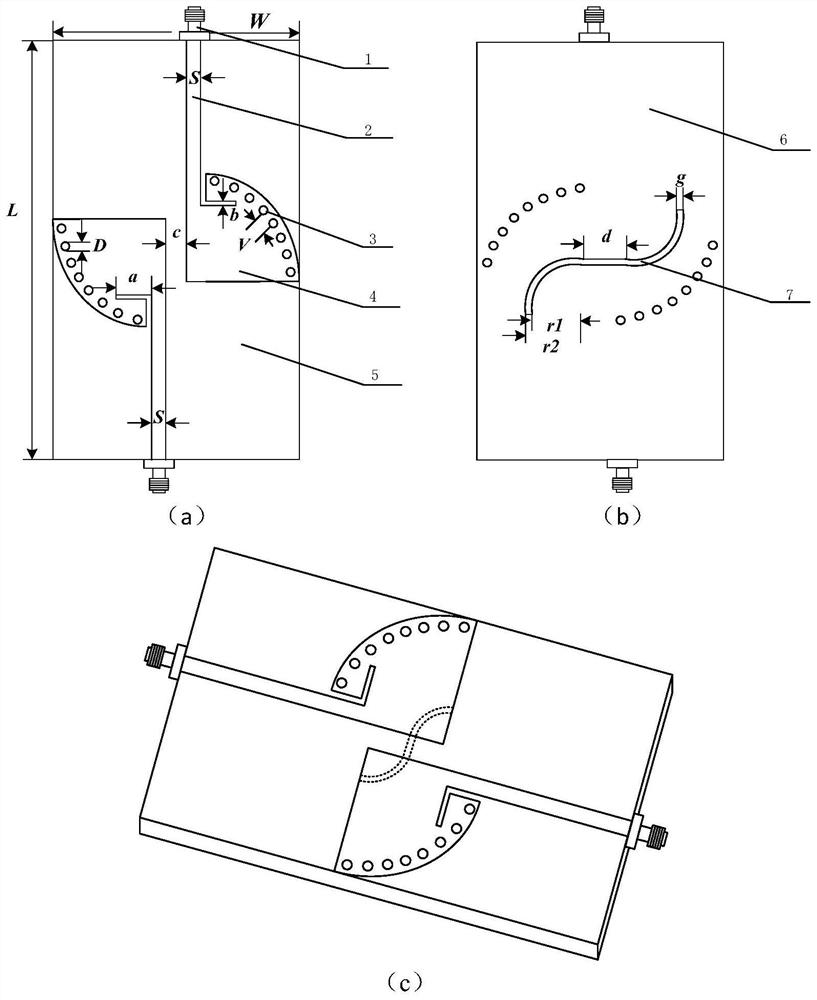
[0034] like figure 1 Shown is a schematic structural diagram of the present invention. The sensor of the present invention is a two-port device, which specifically includes the following:

[0035] The top layer includes two units with the same structure, each unit includes a metal patch 4, a microstrip line 2 and an SMA connector 1;

[0036] The middle layer is Rogers 4350 dielectric board 5;

[0037] The bottom layer includes a metal sheet 6 and a grooved CSRR structure 7;

[0038] The metal patch is provided with a number of metal through holes 3 arranged at equal distances (preferably at a distance of 10°) along the fan-shaped arc edge, for coupling the bottom metal sheet;

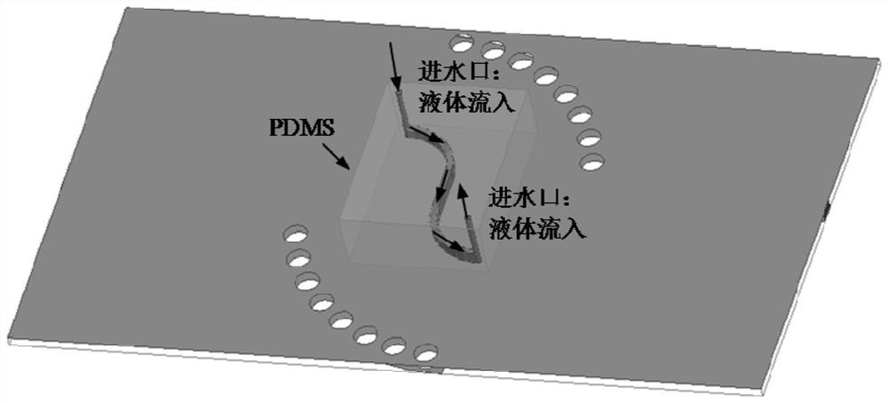
[0039] When in use, turn the sensor upside down, place PDMS with microfluidic channel dug inside on CSRR groove ring 7, inject 10% concentration at 10% con...


PUM

PropertyMeasurementUnit
widthaaaaaaaaaa
thicknessaaaaaaaaaa
lengthaaaaaaaaaa

Abstract

The invention discloses a reconfigurable quarter-mode substrate integrated waveguide microwave microfluidic sensor. The top layer includes two units with the same structure, and each unit includes metal patches, microstrip lines and SMA connectors; the middle layer is a dielectric plate; the bottom layer includes metal sheets and grooved CSRR structures. The metal patch is a quarter-circle fan-shaped structure. In each quarter-circle fan-shaped structure, the field strength near the center of the two perpendicular right-angle sides is the strongest. For radiation, the CSRR is designed just below the two quarter-circle fan-shaped structures, and the PDMS with the microfluidic channel dug in advance is placed just below the CSRR, so that the electric field of radiation can pass through the PDMS to the greatest extent. liquid, thereby increasing the sensitivity of the sensor. The volume of liquid required to pass through the PDMS is small, which avoids waste of sample liquid and prevents environmental pollution.

Description

technical field [0001] The invention belongs to the field of microwave technology, and relates to a sensor excited by a microstrip line, in particular to a miniaturized microwave sensor based on a substrate integrated waveguide (SIW) for measuring the dielectric constant of an ethanol solution. Background technique [0002] Ethanol has a wide range of applications in pharmaceuticals, medical diagnostics, academia, and the beverage industry, where low-cost, miniaturized, potentially safe, and highly sensitive sensor devices operating at ambient temperatures must be available to accurately Analyze and monitor ethanol concentrations. Therefore, how to accurately and quickly measure the dielectric constant of liquids has become a hot topic of common concern in both academia and industry. [0003] In recent years, electrochemical sensors, as state-of-the-art sensors, have made outstanding contributions in detecting ethanol concentration. In this type of sensor, the resistance o...

Claims


Application Information

Patent Timeline
Patent Type & Authority Patents(China)
IPC IPC(8): G01R27/26H01P5/12
CPCG01R27/2635H01P5/12
Inventor 赵文生范立超王大伟陈世昌王高峰
Owner HANGZHOU DIANZI UNIV
Why Eureka
Try Eureka