Integral abutment based on corrugated steel plates and construction method thereof

An integral abutment and corrugated steel web technology, which is applied in bridges, bridge parts, bridge construction, etc., can solve problems such as unfavorable structures and complex stress conditions, and achieve the effect of prolonging service life and ensuring vertical bearing capacity

Pending Publication Date: 2020-05-15
SHENZHEN MUNICIPAL DESIGN & RES INST
View PDF0 Cites 1 Cited by
  • Summary
  • Abstract
  • Description
  • Claims
  • Application Information

AI Technical Summary

Problems solved by technology

[0003] In the existing integral abutment design, in order to reduce the longitudinal expansion and expansion deformation of the superstructure in the structure due to the constraints of the abutment and its foundation, a large additional stress is generated in the structure, and the large horizontal deformation of the flexible pile foundation is generally used to reduce the stress. Small additional stress, but the flexible pile foundation has to bear the horizontal force and vertical force transmitted by the superstructure, the force situation is more complicated and unfavorable to the structure

Method used


Image

  • Integral abutment based on corrugated steel plates and construction method thereof
  • Integral abutment based on corrugated steel plates and construction method thereof
  • Integral abutment based on corrugated steel plates and construction method thereof

Examples


Embodiment 1

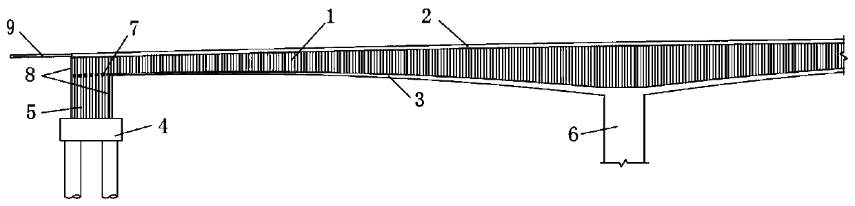
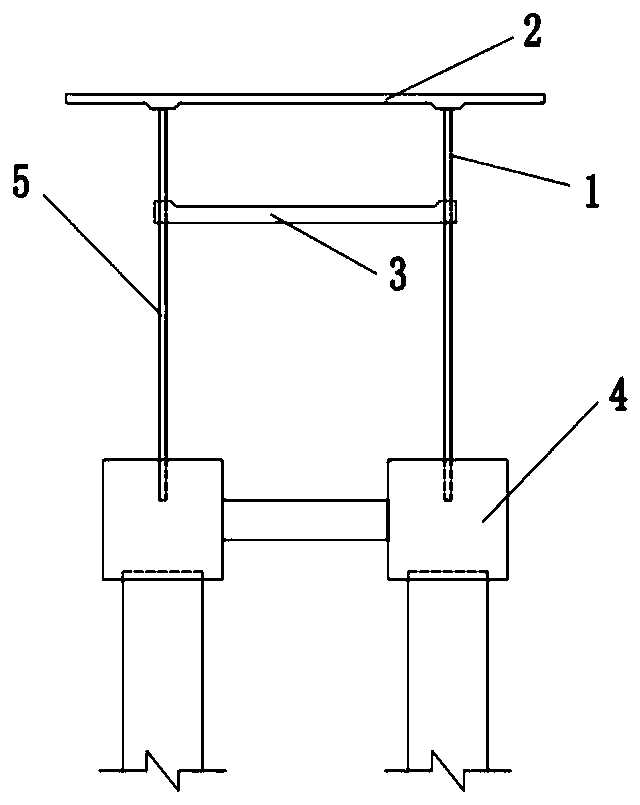
[0038] Such as Figure 1 to Figure 3 As shown: the integral abutment based on corrugated steel plates in this embodiment includes a box girder and several abutment foundations 4 for supporting the box girder. The box girder includes a concrete roof 2, a concrete bottom 3 and a corrugated rigid web. The slabs are respectively connected to the concrete top slab 2 and the concrete bottom slab 3; the end of the corrugated steel web is connected to the abutment foundation 4 through the corrugated steel plate group, and the bottom end of the middle part of the corrugated steel web 1 extends downward and is inserted into the pier 6. In this embodiment, the corrugated steel plate group includes only one corrugated steel plate 5 .

[0039] The box girder includes at least two corrugated steel webs 1, and the corrugated steel webs 1 are connected with the concrete top plate 2 and the concrete bottom plate 3 of the box girder through perforated steel plates and / or welding nails to form a...

Embodiment 2

[0053] Such as Figure 4 As shown, this embodiment provides an integral abutment based on corrugated steel plates. Compared with Embodiment 1, the difference lies in that the corrugated steel web 1 of the box girder in this embodiment corresponds to the corrugated steel plate group of the abutment It includes two or three corrugated steel plates 5 parallel to each other.

Embodiment 3

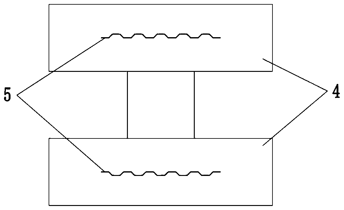
[0055] Such as Figure 5 As shown, the difference between the present embodiment and the first embodiment is that: the corrugated steel plate 5 in the present embodiment is provided with a vertical stiffener 10, and the stiffener 10 is a plate rib or a T rib.


PUM


Abstract

The invention discloses an integral abutment based on corrugated steel plates and a construction method of the integral abutment, the integral abutment comprises a box girder and a plurality of abutment foundations for supporting the box girder, the box girder comprises a concrete top plate, a concrete bottom plate and corrugated steel webs, and the corrugated steel webs are respectively connectedwith the concrete top plate and the concrete bottom plate; the corrugated steel webs are connected with the abutment foundation through the corrugated steel plate sets, and / or the bottom ends of thecorrugated steel webs directly extend downwards and are inserted into the bridge piers. Each corrugated steel plate set comprises a plurality of parallel corrugated steel plates. The construction method comprises the steps of manufacturing the corrugated steel webs in a factory, constructing pile foundations and abutment foundations, constructing corrugated steel plates, constructing box girder sections at the upper part of the abutment, constructing end cross beams, constructing corrugated steel web combined box girder sections, constructing box girder closure sections and the like. The integral abutment provided by the invention not only has large vertical bearing capacity, but also has proper horizontal displacement.

Description

technical field [0001] The invention relates to the technical field of construction engineering, in particular to an integral abutment based on corrugated steel plates and a construction method thereof. Background technique [0002] The problems of bridge expansion devices and maintenance problems have always existed. When multi-span bridges adopt continuous structures, the amount of expansion and contraction at the abutment becomes larger, and the requirements for expansion devices are higher, and the defects are more prominent. The significance of adopting seamless bridges also follows. increase. [0003] In the existing integral abutment design, in order to reduce the longitudinal expansion and expansion deformation of the superstructure in the structure due to the constraints of the abutment and its foundation, a large additional stress is generated in the structure, and the large horizontal deformation of the flexible pile foundation is generally used to reduce the stre...

Claims


Application Information

Patent Timeline
IPC IPC(8): E01D19/02E01D21/00
CPCE01D19/02E01D21/00
Inventor 陈宜言许有胜何晓晖赵秋林松王远洋蒋华王梦雨丁俊凯
Owner SHENZHEN MUNICIPAL DESIGN & RES INST
Why Eureka
Try Eureka