
Cutting method and cutting equipment for solar battery pieces

A technology of solar cell and cutting method, applied in welding equipment, laser welding equipment, metal processing equipment and other directions, can solve problems such as damage at the cutting place, and achieve the effect of smooth fracture surface and fast separation speed

Pending Publication Date: 2020-05-15
NINGXIA XN AUTOMATION EQUIP CO LTD
View PDF1 Cites 14 Cited by
  • Summary
  • Abstract
  • Description
  • Claims
  • Application Information

AI Technical Summary

Problems solved by technology

However, the single-beam laser cutting needs to increase the power of the laser, which will cause great damage to the cutting place.

Method used


Image

  • Cutting method and cutting equipment for solar battery pieces
  • Cutting method and cutting equipment for solar battery pieces
  • Cutting method and cutting equipment for solar battery pieces

Examples


Embodiment 1

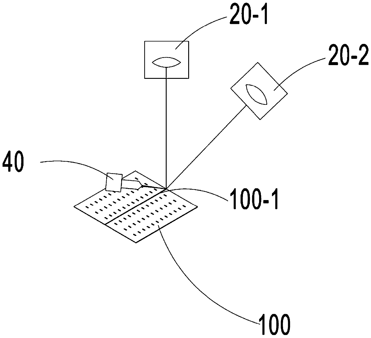
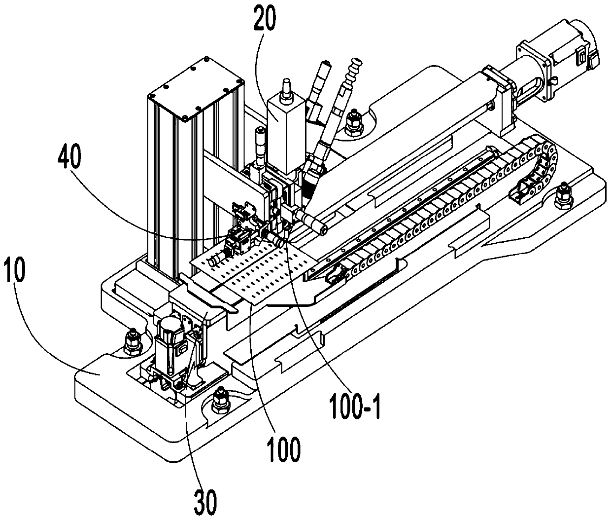
[0045] figure 1 The cutting method of the solar battery sheet is illustrated. At the same time, the first laser beam and the second laser beam are used to focus on the position of the line to be split 100-1 of the battery sheet 100, wherein the first laser beam is drawn on the surface of one end of the battery sheet 100 along the line to be split 100-1 with a certain length. and the dividing line is not enough to break the cell, the second laser beam heats the cell along the line 100-1 to be split, so that the cell 100 is cut off from the line 100-1 to be split, the above two When the two laser beams act on the battery sheet 100 to be cut, a cooling medium is sprayed on the position of the line 100-1 to be split of the battery sheet 100. Due to the effect of the cooling medium, the temperature of the cut place of the battery sheet 100 is always low, and the battery sheet 100 The fracture stress of the material is reduced, therefore, there is no accumulation at the crack of th...

no. 2 example

[0063] Figure 8 It shows a schematic diagram of the moving direction of each component when the battery sheet 100 is cut. The difference between the second embodiment and the first embodiment is that the receiving platform 33 and the battery sheet 100 are fixedly arranged, and the first laser 20-1 and the second laser 20- 2 and the cooling unit 40 can move in the direction of the arrow under the drive of the moving mechanism, so as to complete the cutting of the battery sheet 100.

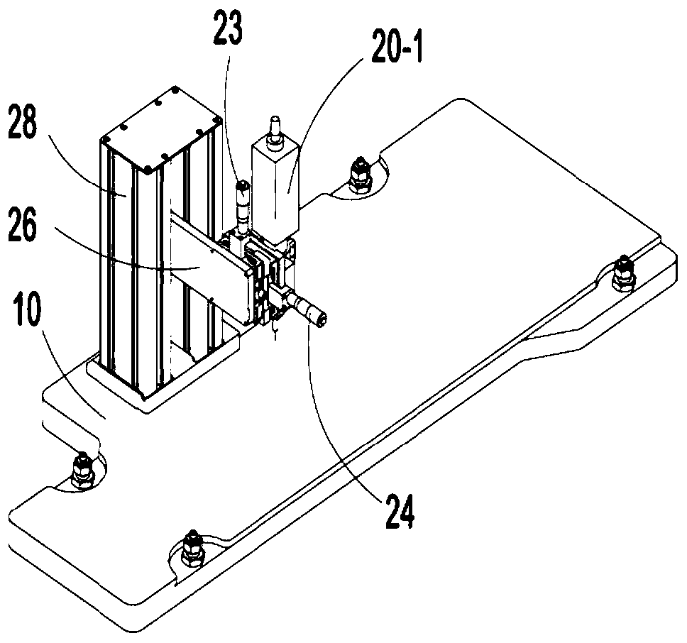
[0064] Working principle: Manually adjust the first laser up and down fine-tuning assembly 23 and the first laser horizontal fine-tuning assembly 24, so that the laser focus point emitted by the first laser 20-1 is located on the line to be split 100-1 in the middle of the cell 100; manually adjust the second The two-laser fine-tuning assembly 25 makes the focal point of the laser emitted by the second laser 20-2 coincide with the focal point of the first laser. Manually adjust the front and rear...


PUM


Abstract

The invention provides a cutting method and cutting equipment for solar battery pieces. In the method, two beams of lasers are mainly adopted to be aligned to to-be-split lines of battery pieces to achieve cutting, meanwhile, a cooling portion sprays a cooling medium to the split lines, so that the battery pieces are cut under small internal stress, and no accumulated object is formed at the splitlines. The equipment adopting the method mainly comprises a fixe frame used for mounting of components, a battery piece transporting portion used for conveying the battery pieces so as to enable thesolar battery pieces to move relative to the focusing point of the first laser beam and the second laser beam, a laser assembly used for generating the first laser beam and the second laser beam and the cooling portion used for spraying the cooling medium to the split lines or points of the battery pieces.

Description

technical field [0001] The invention relates to a method for processing a solar cell, in particular to a method for cutting a solar cell. The invention also relates to special cutting equipment used in the cutting method. Background technique [0002] In recent years, the component industry has developed rapidly. Through continuous experimental research, major component factories have found that the "de-whitening" technology can more effectively improve the efficiency of components, reduce the cost of electricity and increase the efficiency. Therefore, "de-whitening" The research and development of technology has greatly promoted the development of high-efficiency module packaging technology in the photovoltaic industry, and is unanimously optimistic by the industry. [0003] "De-whitening" technology is more common than conventional component technology. "De-whitening" technology is also called splicing, merging, lamination, etc. It optimizes the structure of the component...

Claims


Application Information

Patent Timeline
Patent Type & Authority Applications(China)
IPC IPC(8): B23K26/38B23K26/40B23K26/60B23K26/70
CPCB23K26/40B23K26/60B23K26/703B23K26/38
Inventor 雍刚葛清越石福仓
Owner NINGXIA XN AUTOMATION EQUIP CO LTD
Learn More