
Monitoring system and method for deep settlement of soil behind shield tunnel wall

A technology of shield tunneling and monitoring system, which is applied to measurement devices, surveying and navigation, height/level measurement, etc., can solve the problems of low measurement accuracy, inability to open holes freely, and inability to measure in real time, and achieve high monitoring accuracy, Accurate and reliable monitoring results, strong anti-electromagnetic interference effect

Active Publication Date: 2020-05-12
SHENZHEN UNIV
View PDF5 Cites 1 Cited by
  • Summary
  • Abstract
  • Description
  • Claims
  • Application Information

AI Technical Summary

Problems solved by technology

[0004] Although the traditional displacement meter has the advantages of cheap price and easy operation, its large size, low measurement accuracy and inability to measure in real time make it unusable in many scenarios
[0005] Measuring the internal deformation of the surrounding rock of a cavern with a multi-point displacement meter is a relatively common measurement method at present, as shown in a method for installing a multi-point displacement meter and burying the grouting provided by the patent number CN103290827A. The shield tunnel segment is a sealed body and cannot freely open holes

Method used


Image

  • Monitoring system and method for deep settlement of soil behind shield tunnel wall
  • Monitoring system and method for deep settlement of soil behind shield tunnel wall
  • Monitoring system and method for deep settlement of soil behind shield tunnel wall

Examples


Embodiment Construction

[0048]The application will be described in further detail below in conjunction with the accompanying drawings.

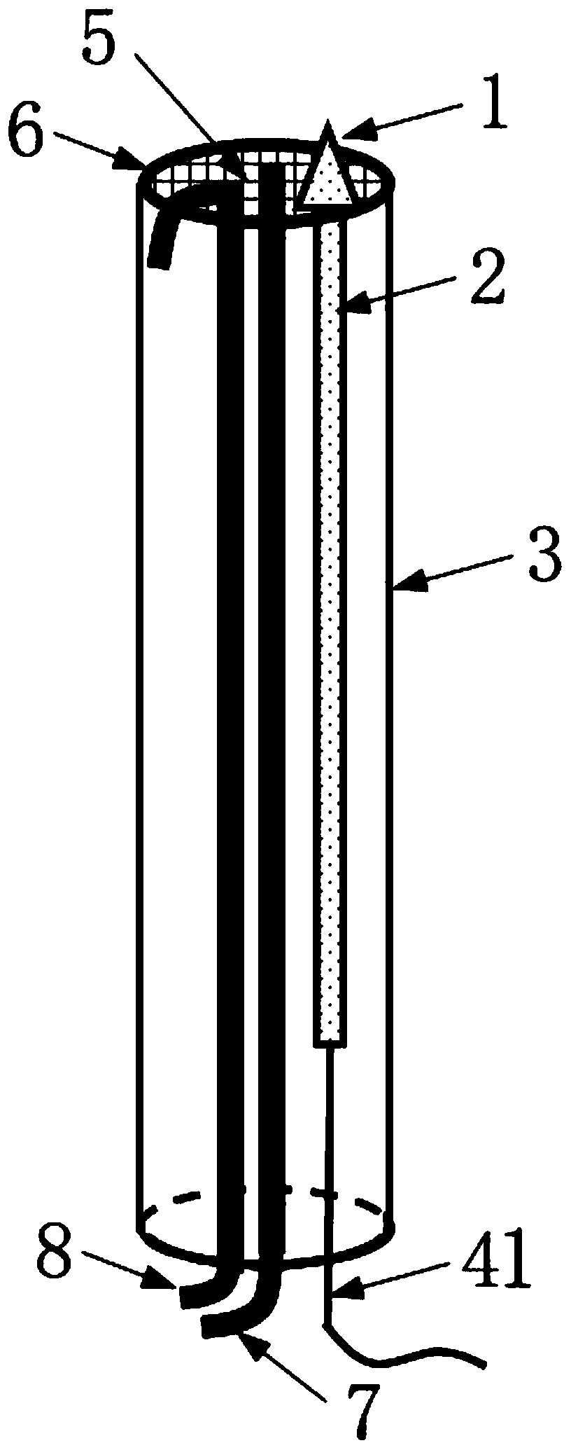
[0049] figure 1 A perspective view showing a data acquisition device in a monitoring system for deep subsidence of soil behind a shield tunnel wall.

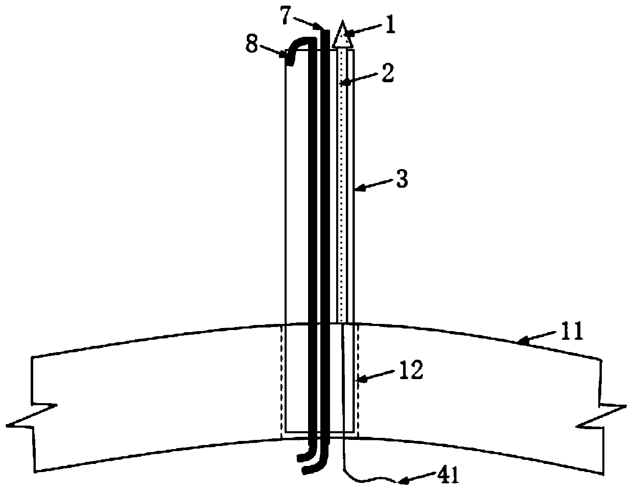
[0050] Such as figure 1 As shown, the data acquisition device includes an anchor head, an LCI displacement meter, a PVC pipe, a first optical fiber cable, a filter screen, a collar, a first micro-grouting pipe, and a second micro-grouting pipe, wherein the LCI displacement meter is placed in the PVC pipe , the upper end is just connected to the anchor head, the lower end is connected to the data processing system through the first optical fiber cable, the anchor head is inserted into the PVC pipe and inserted into the soil in situ, the collar is placed on the PVC pipe, and a filter screen is embedded in the middle, The first micro-grouting pipe and the second micro-grouting pipe are bundled and placed in the PVC pip...


PUM


Abstract

The invention aims to provide a monitoring system and method for deep settlement of soil behind a shield tunnel wall. The monitoring system comprises a data collection device and a data processing system. The data collection device comprises an anchor head, an LCI displacement meter, a PVC pipe, a first optical fiber cable, a filter screen, a lantern ring, a first micro grouting pipe and a secondmicro grouting pipe, wherein the LCI displacement meter is arranged in the PVC pipe, the upper end of the LCI displacement meter is rigidly connected with the anchor head, the lower end of the LCI displacement meter is connected with the data processing system through the first optical fiber cable, the anchor head extends into the PVC pipe and is inserted into in-situ soil, the lantern ring sleeves the PVC pipe, the filter screen is embedded in the middle, and the first micro grouting pipe and the second micro grouting pipe are bound in the PVC pipe. According to the scheme, the problem that drilling measurement cannot be conducted under the existing shield tunnel segment sealing condition is solved; meanwhile, the optical fiber sensing technology has the advantages of being high in precision, high in electromagnetic interference resistance and suitable for long-term monitoring of tunnels, the requirement for automatic monitoring can be completely met, and the optical fiber sensing technology can be applied to actual engineering conditions.

Description

technical field [0001] The present application relates to the technical field of tunnel engineering monitoring, in particular to a monitoring system and method for monitoring deep subsidence of soil behind a shield tunnel wall based on low-coherence interferometry (LCI) technology. Background technique [0002] 3D printing technology, as an emerging technology of rapid prototyping, has developed rapidly in recent years. way to get 3D solids. [0003] As the construction of shield tunnels has gradually become the main construction form of subway, underwater and other traffic tunnels, in recent years, with the large-scale construction of underground shield tunnels, the disasters caused during its construction and operation have become a hot spot of concern, such as Disaster problems such as concrete deterioration, uneven damage to lining, and voids behind, many of which are related to deformation and settlement of soil. [0004] Although the traditional displacement meter ha...

Claims


Application Information

Patent Timeline
Patent Type & Authority Applications(China)
IPC IPC(8): G01C5/00
CPCG01C5/00
Inventor 付艳斌李云鹏陈湘生
Owner SHENZHEN UNIV
Learn More