
Ship window structure

A window structure and ship technology, applied in ship windows, ship parts, ship construction, etc., can solve problems such as reducing structural fatigue life, window glass breakage, fatigue cracks, etc., to increase force capacity and firmness, and reduce stress levels , Increase the effect of structural strength

Active Publication Date: 2020-05-12
OCEAN UNIV OF CHINA
View PDF10 Cites 5 Cited by
  • Summary
  • Abstract
  • Description
  • Claims
  • Application Information

AI Technical Summary

Problems solved by technology

This window installation method simply meets the installation requirements, and the welding strength at the joint is very low, which poses a large safety hazard
[0003] The function and layout requirements of offshore engineering platforms are getting higher and higher, and the size of windows is getting bigger and bigger, resulting in a significant reduction in the shear bearing area of ​​the hull structure, which greatly reduces the strength of the hull structure, especially at the corners of the window openings , there is a large stress concentration phenomenon, which has a great influence on the strength and fatigue of the structure
On the other hand, windows are no longer limited to non-load-bearing secondary structures. Windows are also required to be installed on many main load-bearing bulkheads to meet the functional requirements of ships and platforms. For these load-bearing tanks The wall, especially the bulkhead that bears a large dynamic load, is prone to fatigue cracks if the existing window structure and single-side fillet welding connection form are used, which reduces the fatigue life of the structure and cannot meet the normal strength and fatigue requirements of the structure. At the same time, when the load-bearing bulkhead is deformed by force, it is easy to deform the window frame, forming extrusion and shearing on the window glass, causing the window glass to break

Method used


Image

  • Ship window structure
  • Ship window structure
  • Ship window structure

Examples


Embodiment Construction

[0037] In order to make the purpose, technical solutions and advantages of the embodiments of the present invention more clear, the technical solutions in the embodiments of the present invention will be clearly and completely described below in conjunction with the drawings in the embodiments of the present invention.

[0038] In the description of the present invention, it should be noted that the orientation or positional relationship indicated by the terms "upper", "lower", "inner", "outer" etc. is based on the positional relationship of window structure installation. The terminology is only used to describe the present invention and simplify the description, but does not indicate or imply that the device or element referred to must have a specific orientation, be constructed and operated in a specific orientation, and thus should not be construed as limiting the present invention. In addition, the terms "first", "second", and "third" are used for descriptive purposes only,...


PUM


Abstract

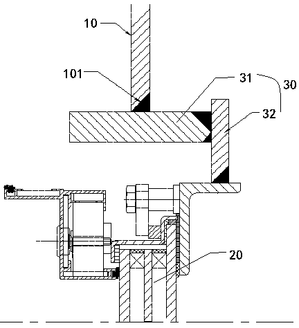
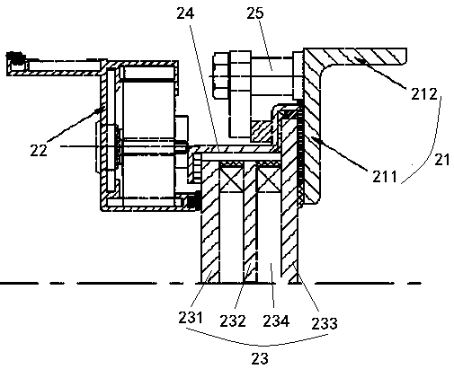
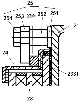
The invention discloses a ship window structure which is mounted and fixed on a bulkhead of a ship, and a mounting opening is formed in the bulkhead; the ship window structure comprises a window body;a mounting connecting structure which is connected and fixed between the window body and the bulkhead; the mounting connecting structure is provided with a first connecting frame fixedly arranged onthe bulkhead, and the first connecting frame extends in the direction perpendicular to the bulkhead at the mounting opening and is symmetrically arranged inside and outside. By arranging the mountingconnecting structure, the stress level of the mounting opening area of the bulkhead is effectively reduced, the strength problem of the mounting opening is solved, the structural strength of the window structure after mounting is improved, and the stress capacity and firmness after mounting are improved. The first connecting frame is arranged to be in a barrel shape symmetrically arranged in the inner-outer direction, the stress area in the inner-outer direction is increased by extending in the inner-outer direction, the structural strength of the mounting connecting structure is improved, andit is guaranteed that the structural strength of the ship bulkhead is improved after the window structure is installed.

Description

technical field [0001] The invention belongs to the technical field of ships, and in particular relates to a window structure of a ship. Background technique [0002] At present, during the design and construction of ships and offshore engineering platforms, windows are provided as standard components by relevant manufacturers according to the required size. Marine windows should be integrated with their glass and window covers to effectively ensure watertightness or airtightness. Require. The outer frame of the window is connected and fixed with the hull, and the commonly used connection method is to use single-sided fillet welding to connect the window with the hull structure as a whole. This window installation method simply meets the installation requirements, and the welding strength at the joint is very low, which poses a relatively large safety hazard. [0003] The function and layout requirements of offshore engineering platforms are getting higher and higher, and ...

Claims


Application Information

Patent Timeline
IPC IPC(8): B63B19/00B63B19/02
CPCB63B19/00B63B19/02B63B2019/0007
Inventor 李德江孟珣唐品
Owner OCEAN UNIV OF CHINA
Learn More