
Medical vacuum system sterilization treatment device

A technology of sterilization treatment and vacuum system, which is applied in the direction of water supply equipment, waste disinfection or sterilization methods, sanitary equipment for toilets, etc., can solve the problems of large investment in equipment, large investment, complex system structure, etc., and achieve guaranteed The effect of meeting discharge standards, increasing contact time, and improving treatment efficiency

Pending Publication Date: 2020-05-12
杭州鼎岳空分设备有限公司
View PDF3 Cites 0 Cited by
  • Summary
  • Abstract
  • Description
  • Claims
  • Application Information

AI Technical Summary

Problems solved by technology

For example, the patent number "201310689963.2" introduces a hospital medical waste gas treatment and safe discharge system, including a dust collector connected in sequence, a closed heater, a reactor, a filter, a main induced draft fan and a circulating fan; at the same time, the temperature is arranged in the system , pressure and flow sensors, and process the measurement signal through the measurement module; according to the measurement signal, the automatic control module adjusts the working status of the dust collector, closed heater, reactor and fan equipment to meet the needs of the current medical waste gas treatment; although The system has a wide range of treatment of medical waste gas, and the treatment effect is good; but the investment in equipment is large, the investment is large, and the floor area is large, and the requirements for the site are high. The use of heat sterilization also has problems such as high energy consumption and low treatment efficiency.
Patent No. "201711219624.2" introduces a hospital department exhaust air treatment device and treatment method. The treatment device includes a primary filter unit, a sterilization and disinfection unit, a secondary filter unit and an ultraviolet sterilization and disinfection unit. The primary filter unit uses an electrostatic precipitator. The air inlet of the electrostatic precipitator communicates with the exhaust air outlet of the hospital department; by using a specially configured disinfectant in the sterilization and disinfection unit, the purpose of sterilization is achieved; although most bacteria can be killed, due to the complex composition of bacteria, it is still There will be hidden dangers of incomplete sterilization, and the operation of the equipment is troublesome and costly
Another example is the patent number "201711424909 .X", which introduces a hospital waste gas treatment device, including a suction hood with an electric valve connected through pipelines, a waste gas transportation pipeline system, a vacuum suction system, a Venturi mixer, a water distributor, The aerobic biological deodorization system, waste gas drainage system and sterilizing pool have the characteristics of rapid waste gas treatment, wide range of waste gas treatment, and high treatment efficiency, but there are also defects such as large equipment investment, complex system structure, and high maintenance costs.
[0004] Therefore, most of the existing sterilization and sterilization equipment for medical vacuum pipeline systems have problems such as high investment in equipment, large investment, long construction period, and low processing efficiency.
In particular, the sudden attack of the new coronavirus in 2019 has brought a severe test to my country's medical system. The traditional filter bacteria treatment cannot filter the new coronavirus well, and the exhaust outlet of the vacuum pipeline in the hospital needs to be strictly sterilized. , anti-virus treatment, before it can be discharged, and the development of a set of medical waste gas treatment devices that can be put into use quickly, occupy a small area, and have good sterilization and anti-virus effects is an important issue that domestic medical equipment manufacturers need to solve.

Method used


Image

  • Medical vacuum system sterilization treatment device
  • Medical vacuum system sterilization treatment device
  • Medical vacuum system sterilization treatment device

Examples


Embodiment Construction

[0023] Now in conjunction with the accompanying drawings, the preferred embodiments of the present invention will be described in detail.

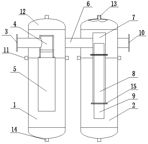
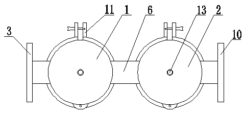
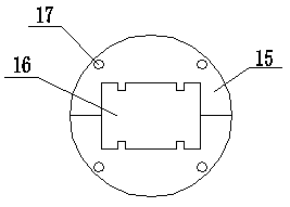
[0024] Such as figure 1 As shown, a medical vacuum system sterilization treatment device of this embodiment includes a first tank body 1 and a second tank body 2, both of which are cylindrical in structure, divided into It is an upper part and a lower part; the side of the first tank body 1 is provided with an air inlet 3, and the air inlet 3 is connected to the first sealing joint 4, and the lower end of the first sealing joint 4 is connected to the bacterial filter 5; The upper ends of the first tank body 1 and the second tank body 2 are provided with a connecting pipe 6, and the connecting pipe 6 is connected to a second sealing joint 7, and the second sealing joint 7 is connected to an intermediate pipe 8; the second tank body A sterilizer 9 is arranged inside the tank 2, and the sterilizer 9 is fixed on the second sealing joint 7 and...


PUM

PropertyMeasurementUnit
Apertureaaaaaaaaaa

Abstract

The invention belongs to the technical field of hospital waste gas treatment, and aims at providing a medical vacuum system sterilization treatment device which comprises a first tank body and a second tank body, and the first tank body and the second tank body are each of a cylindrical structure; an air inlet is formed in the side face of the first tank body and connected with a first sealing joint, and the lower end of the first sealing joint is connected with a bacterial filter; a connecting pipe is arranged at the upper ends of the first tank body and the second tank body, the connecting pipe is connected with a second sealing joint, and the second sealing joint is connected with a middle pipe; a sterilizer is arranged in the second tank body; the sterilizer is fixed on the second sealing joint and the middle pipe; and an exhaust port is further formed in the side surface of the second tank body. The device has the characteristics of simple structure, convenience in installation, high sterilization efficiency, low investment cost and the like, and can be widely applied to the field of hospital waste gas treatment.

Description

technical field [0001] The invention belongs to the technical field of hospital waste gas treatment, and in particular relates to a medical vacuum system sterilization treatment device. Background technique [0002] The medical negative pressure system, also known as the central suction system, mainly uses the vacuum pump unit of the central suction station as the negative pressure source to realize the negative pressure value required by the pipeline of the suction system. It is used in the operating room, rescue room, treatment room and each ward Suction is generated at the terminal, which is mainly used to suck out sputum, blood, pus and other pollutants in the patient's body. The components of these pollutants are complex and contain a large number of bacteria and viruses, which need to be treated to meet the standards before they can be discharged. [0003] At present, most of the existing medical waste gas treatment adopts high-temperature sterilization treatment, and...

Claims


Application Information

Patent Timeline
IPC IPC(8): A61L11/00A61L2/14
CPCA61L2/14A61L11/00
Inventor 徐利民周建军张龙解兵赵佳
Owner 杭州鼎岳空分设备有限公司
Learn More