Driving method of switching tube driving circuit

A driving circuit and driving method technology, applied in the direction of electrical components, output power conversion devices, etc., can solve the problem of not guaranteeing stable opening and closing, etc.

Active Publication Date: 2020-05-08
SHANGHAI UNITED IMAGING HEALTHCARE
View PDF7 Cites 0 Cited by
  • Summary
  • Abstract
  • Description
  • Claims
  • Application Information

AI Technical Summary

Problems solved by technology

[0005] Based on this, it is necessary to provide a driving method for a switching tube driving circuit in view of the problem that the traditional switching tube driving circuit and driving method cannot ensure that each switching tube unit in the two series switching branches is simultaneously and stably opened and closed.

Method used


Image

  • Driving method of switching tube driving circuit
  • Driving method of switching tube driving circuit
  • Driving method of switching tube driving circuit

Examples


Embodiment Construction

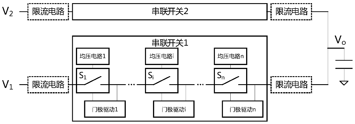
[0050] In order to make the purpose, technical solution and advantages of the present application clearer, the present application will be further described in detail below in conjunction with the accompanying drawings and embodiments. It should be understood that the specific embodiments described here are only used to explain the present application, and are not intended to limit the present application.

[0051] The present application provides a driving method for a switching tube driving circuit.

[0052] It should be noted that the driving method of the switching transistor driving circuit provided in the present application does not limit its application field and application scenario. The driving method of the switching tube driving circuit provided in the present application is applied to all switching tube driving circuits with high start-up voltage and capable of converting low-frequency voltage to high-frequency voltage. Optionally, the driving method of the switc...


PUM


Abstract

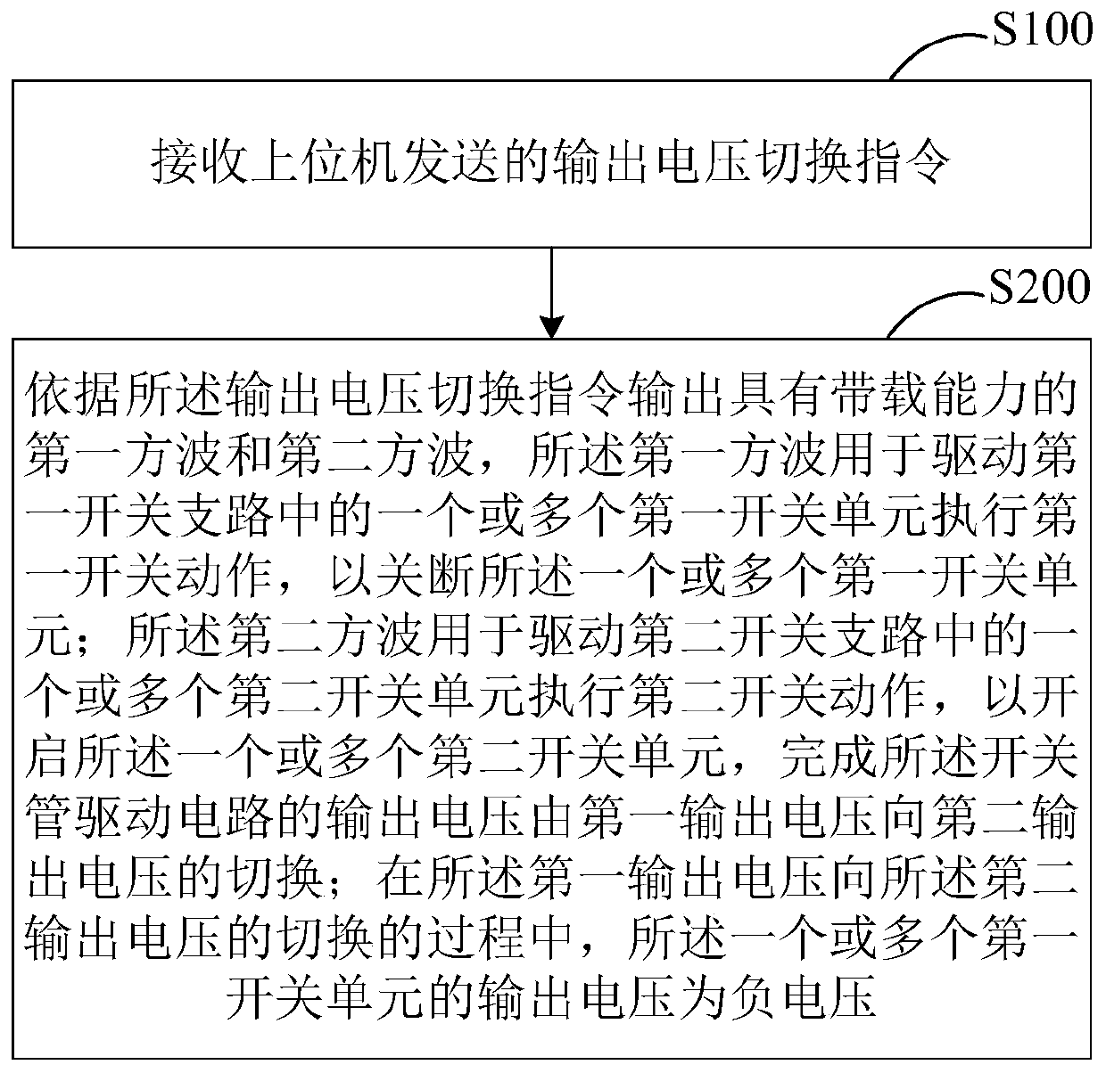
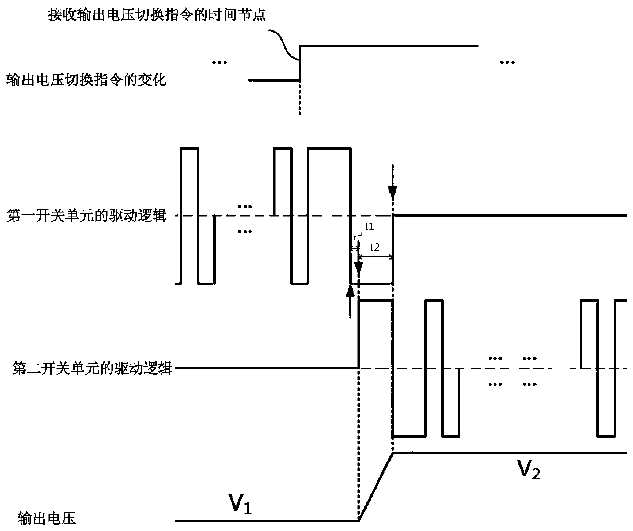
The invention relates to a driving method of a switching tube driving circuit. The driving method comprises the steps that a driving unit in the switching tube driving circuit generates a first squarewave and a second square wave with loading capacity according to an output voltage switching instruction sent by an upper computer; one or more first switch units in a first switch branch and one ormore second switch units in a second switch branch are driven to execute switching actions at the same time, so as to complete the switching from a first output voltage to a second output voltage. Inthe voltage switching process, the output voltage of one or more first switch units is negative voltage; therefore, it is ensured that the first switch branch and the second switch branch are not mistakenly conducted; the first switch units are not mistakenly conducted, and the second switch units are not mistakenly conducted, so it is ensured that the first output voltage is stably and reliably switched to the second output voltage, and a switch tube device in the switch tube driving circuit is not damaged.

Description

technical field [0001] The present application relates to the technical field of switch tube drive, in particular to a drive method for a switch tube drive circuit. Background technique [0002] In a CT system (Computed-Tomography, ie, computerized tomography), the femtofocus technology can play a role in improving the spatial resolution. The flying focus, that is, the focus of the electron beam on the surface of the target disk in the tube, is constantly switched between multiple positions according to the system requirements. [0003] The basic principle of realizing the flying focus based on the electric field is: there are two grids at the cathode of the bulb, and according to the system requirements, a fast-changing voltage is output to the grid through a dedicated power supply, thereby forming a fast-changing electric field between the grid and the cathode of the bulb. Under the action of the fast-changing electric field, the focus position of the electron beam emitte...

Claims


Application Information

Patent Timeline
IPC IPC(8): H02M1/088
CPCH02M1/088
Inventor 吴景林舒志辉陈青昌褚旭
Owner SHANGHAI UNITED IMAGING HEALTHCARE
Why Eureka
Try Eureka