A lithium battery using a lightweight current collector

A current collector and lithium battery technology, which is applied in the direction of lithium batteries, battery electrodes, electrode carriers/current collectors, etc., can solve problems such as difficult preparation, reduced mechanical strength of foil materials, and inability to meet lithium-ion batteries, so as to reduce quality and guarantee Conductivity, effect that facilitates adhesion

Active Publication Date: 2022-03-11
HEFEI GUOXUAN HIGH TECH POWER ENERGY
View PDF10 Cites 0 Cited by
  • Summary
  • Abstract
  • Description
  • Claims
  • Application Information

AI Technical Summary

Problems solved by technology

[0002] Traditional lithium-ion battery current collectors use aluminum foil for the positive electrode and copper foil for the negative electrode. With the development of technology and the drive of national policies, lightweight, flexible and high-energy-density lithium-ion batteries have become the direction of pursuit. Metal foil materials are used in Lithium-ion batteries occupy an effective volume. Traditionally, copper / aluminum is used as the current collector. The mass of the current collector is about 8%~14%. The common method is to gradually reduce the thickness of copper foil / aluminum foil. Currently, the thinnest foil The materials are 10μm aluminum foil and 5μm copper foil, but subject to the front-end foil production process, the thinner it is, the more difficult it is to prepare. At the same time, the reduced thickness will lead to a decrease in the mechanical strength of the foil, which cannot meet the requirements of the lithium-ion battery production and preparation process.

Method used


Image

  • A lithium battery using a lightweight current collector
  • A lithium battery using a lightweight current collector

Examples


Embodiment Construction

[0024] In the description of the present invention, unless otherwise specified, the orientation or positional relationship indicated by the terms "upper", "lower", "left", "right", "front", "rear", etc. are only for describing the present invention and simplifying the description, rather than Nothing indicating or implying that the referred device or structure must have a particular orientation should not be construed as limiting the invention. In addition, the terms "first", "second", etc. are used for descriptive purposes only, and should not be construed as indicating or implying relative importance.

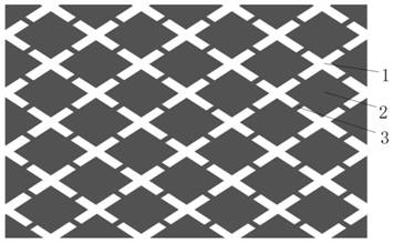
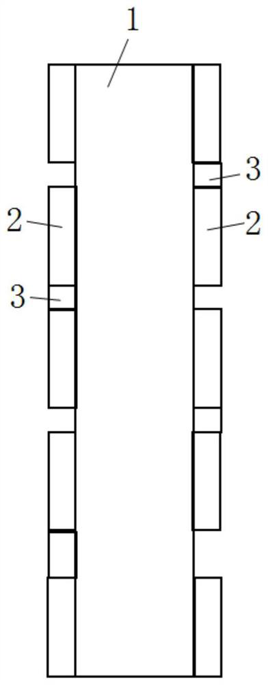
[0025] Such as figure 1 As shown, a lithium battery using a lightweight current collector according to the present invention includes a positive electrode sheet, a separator, and a negative electrode sheet in a stacked or wound manner, the positive electrode sheet includes a positive electrode current collector, and the negative electrode sheet The sheet includes a negative ...


PUM

PropertyMeasurementUnit
thicknessaaaaaaaaaa
thicknessaaaaaaaaaa
thicknessaaaaaaaaaa

Abstract

The invention discloses a lithium battery using a lightweight current collector, which comprises a positive electrode sheet, a diaphragm, and a negative electrode sheet in a stacked or wound manner, the positive electrode sheet includes a positive electrode collector, and the negative electrode sheet includes a negative electrode sheet. Fluid, the positive electrode current collector and / or the negative electrode current collector are composed of a conductive film base layer and a metallized film layer, the thickness of the conductive film base layer is 5 to 20 μm, and the conductivity of the conductive film base layer is 1 to 100 s / cm, the thickness of the metallized film layer is 0.2-2 μm, the metallized film layer of the positive electrode current collector is an aluminum layer or a nickel layer, and the metallized film layer of the negative electrode current collector is a copper layer, an iron layer and a tungsten layer one of the layers. In the present invention, the positive electrode current collector and / or the negative electrode current collector are composed of a conductive film base layer and a metallized film layer, wherein the conductive film base layer is prepared from a polymer substrate, so as to effectively reduce the current collector while realizing the current collector function. The quality of the collector achieves the purpose of reducing the weight of the current collector.

Description

technical field [0001] The invention belongs to the technical field of batteries, and in particular relates to a lithium battery using a lightweight current collector. Background technique [0002] Traditional lithium-ion battery current collectors use aluminum foil for the positive electrode and copper foil for the negative electrode. With the development of technology and the drive of national policies, lightweight, flexible and high-energy-density lithium-ion batteries have become the direction of pursuit. Metal foil materials are used in Lithium-ion batteries occupy an effective volume. Traditionally, copper / aluminum is used as the current collector. The mass of the current collector is about 8%~14%. The common method is to gradually reduce the thickness of copper foil / aluminum foil. Currently, the thinnest foil The materials are 10 μm aluminum foil and 5 μm copper foil, but subject to the front-end foil production process, the thinner it is, the more difficult it is to ...

Claims


Application Information

Patent Timeline
Patent Type & Authority Patents(China)
IPC IPC(8): H01M4/66H01M10/052
CPCH01M4/667H01M4/668H01M4/661H01M10/052Y02E60/10
Inventor 李缜王启岁汪涛张江伟张沿江吴洋洋王晨旭
Owner HEFEI GUOXUAN HIGH TECH POWER ENERGY
Why Eureka
Try Eureka