
Press fit equipment for plywood

A lamination equipment and technology for plywood, applied in the direction of plywood press, veneer press, wood veneer joining, etc. The effect of product quality

Inactive Publication Date: 2020-05-08
ANHUI FUYANG QINGLIN WOOD PROD CO LTD
View PDF0 Cites 10 Cited by
  • Summary
  • Abstract
  • Description
  • Claims
  • Application Information

AI Technical Summary

Problems solved by technology

Existing plywood gluing machines generally apply glue through gluing rollers. In the process of gluing, when the rubber rollers just come out of the glue pool, the glue content is the largest, and as the brushing, the glue content gradually decreases. Small, this will cause uneven glue on the smeared surface of the board, the end close to the glue pool and the end far away, which will affect the bonding quality of the board

Method used


Image

  • Press fit equipment for plywood
  • Press fit equipment for plywood
  • Press fit equipment for plywood

Examples


Embodiment 1

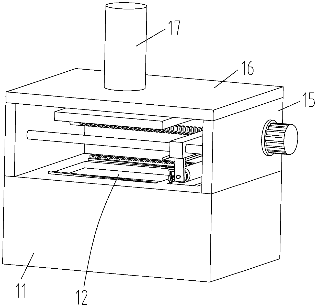
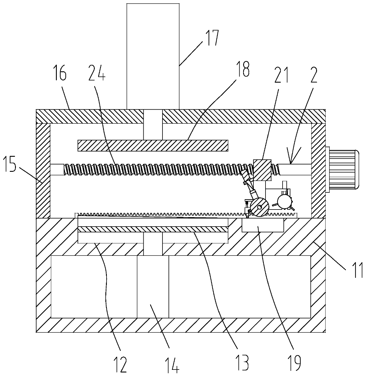
[0028] Such as Figure 1-Figure 9 As shown, a kind of plywood pressing equipment provided by the present invention includes a box body 11, and the upper side of the box body 11 is provided with a placement groove 12, and the plywood that needs to be laminated layer by layer is placed in the placement groove 12, and placed in the groove 12 The support plate 13 is slidably connected, and the inside of the box body 11 is fixedly connected to the support cylinder 14. The telescopic rod of the support cylinder 14 extends into the placement groove 12 and is fixedly connected with the bottom of the support plate 13. After the plywood is placed in one layer, it is glued and placed on the top. After a layer of plywood is pressed, after a single pressing is completed, the supporting plate 13 is lowered by a height of a veneer and then circulated. After the final pressing is completed, the supporting plate 13 pushes all the plywood out of the placement slot 12, and the upper side of the b...

Embodiment 2

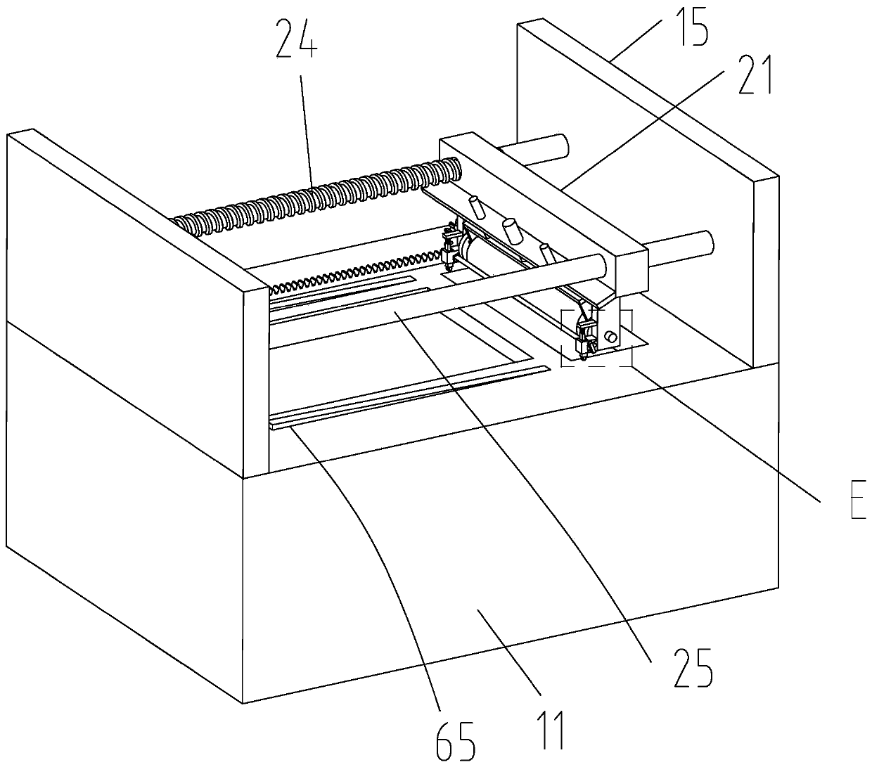
[0033] Such as Figure 6-Figure 11 As shown, on the basis of Embodiment 1, in order to solve the problem that the glue on the edge of the slot 12 solidifies and is difficult to clean, a rubber scraping device 8 is provided on one side of the vertical plate 22. The rubber scraping device 8 includes a support block 81, and the support block 81 Fixedly connected to one side of the vertical plate 22, the middle part of the support block 81 is provided with a third chute 82, and the third chute 82 is slidably connected to the third slider 83, and the middle part of the third slider 83 is rotatably connected to the second rotating shaft 84, and the second One end of the rotating shaft 84 is fixedly connected to the scraping roller 85. The scraping roller 85 includes a roller 851. The outer ring of the roller 851 is provided with a group of elastic sheets 852. The elastic sheets 852 are stainless steel sheets. There are at least three elastic sheets 852, and the rollers The axis of 8...


PUM


Abstract

The invention discloses press fit equipment for a plywood. The equipment comprises a box. The upper side of the box is provided with a gluing device, the gluing device comprises a mobile block, and the mobile block is slidingly arranged between two vertical plates. Two vertical plates are symmetrically and fixedly connected to the bottom of the mobile block, a sponge roller is rotatably connectedbetween the two vertical plates, a mounting block is fixedly connected to one side of each vertical plate, and a press rod is connected between the two mounting blocks and extrudes the sponge roller through an extrusion device. According to the press fit equipment for the plywood, when the mobile block moves in the direction away from a glue tank, second inclined plates make wedge blocks moving onthe second inclined plates gradually move upwards, through the interaction of wedge surfaces, the wedge blocks push second slide blocks to press the sponge roller, the press rod extrudes the glue adsorbed by the sponge roller, the glue directly falls on the surface of the plywood, and the problem is solved that when the sponge roller is applied to painting, the amount of the glue is gradually reduced, and the glue on the plywood is uneven. It is guaranteed that the glue is applied evenly, and the quality of the product is guaranteed.

Description

technical field [0001] The invention relates to the technical field of plywood production, in particular to a plywood pressing device. Background technique [0002] Plywood is a three-layer or multi-layer board-like material that is made of wood sections that are peeled into veneers or sliced ​​into thin wood, and then glued with adhesives. Usually, odd-numbered veneers are used, and adjacent layers of veneers are used. The fiber directions are glued perpendicular to each other. [0003] Plywood gluing machine is one of the main equipment for producing plywood, it is a kind of mechanical equipment that evenly coats the prepared adhesive on the surface of veneer. Existing plywood gluing machines generally apply glue through gluing rollers. In the process of gluing, when the rubber rollers just come out of the glue pool, the glue content is the largest, and as the brushing, the glue content gradually decreases. Small, this will cause uneven glue on the smeared surface of the...

Claims


Application Information

Patent Timeline
IPC IPC(8): B27D1/08B27D3/00B27G11/00
CPCB27D1/083B27D3/00B27G11/00
Inventor 汤瀚袁京金贺祖
Owner ANHUI FUYANG QINGLIN WOOD PROD CO LTD
Learn More