A method for monitoring the state of machine tools
A technology of machine tools and cutting tools, applied in the direction of manufacturing tools, metal processing machinery parts, metal processing equipment, etc., can solve the problems of cutting processing influence and inability to monitor tool status, and achieve the effect of avoiding additional influence
- Summary
- Abstract
- Description
- Claims
- Application Information
AI Technical Summary
Problems solved by technology
Method used
Image

Examples
Embodiment 1
[0084] Embodiment 1: M=1, that is, according to the current signal collected during the first cutting process of the machine tool, the upper and lower boundary curves of the current signal are obtained.
[0085] During specific implementation, when performing step S11 in the above-mentioned monitoring method provided by the present invention, when calculating the root mean square value of each segment current signal, the root mean square value I of each segment current signal can be calculated according to the following formula rms :
[0086]
[0087] Among them, I 1 ,I 2 ...I t is the data point of each current signal, and t is the number of data points.
[0088] In the specific implementation, when performing step S12 in the above-mentioned monitoring method provided by the present invention, according to the calculated root mean square value of each segment current signal, calculate the mean value sum of the N root mean square values corresponding to each N segment ...
Embodiment 2
[0097] Embodiment 2: M>1, for example, M=5, that is, the upper and lower boundary curves of the current signal are obtained according to the current signals collected during the first five cutting processes of the machine tool.
[0098] During specific implementation, when performing step S11 in the above-mentioned monitoring method provided by the present invention, when calculating the root mean square value of each segment current signal, the root mean square value I of each segment current signal can be calculated according to the following formula rms :
[0099]
[0100] Among them, I 1 ,I 2 ...I t is the data point of each current signal, and t is the number of data points.
[0101] In the specific implementation, when performing step S12 in the above-mentioned monitoring method provided by the present invention, according to the calculated root mean square value of each segment current signal, calculate the mean value sum of the N root mean square values corresp...
Embodiment 3
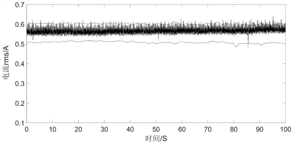
[0111] Embodiment 3: The workpiece material to be processed is Q235, the cutting depth ap=2mm, the cutting width ae=10mm, the rotating speed n=700rpm, and the feed rate f=100mm / min.
[0112] Figure 5 Six groups of upper and lower boundary curves are shown, which are respectively the upper and lower boundary curves of the current signal obtained according to the current signal collected during the first cutting process of the machine tool (such as Figure 5 The first group of curves shown), according to the current signal collected in the second cutting process of the machine tool to obtain the upper and lower boundary curves of the current signal (such as Figure 5 The second group of curves shown), according to the current signal collected in the third cutting process of the machine tool to obtain the upper and lower boundary curves of the current signal (such as Figure 5 The third group of curves shown), according to the current signal collected in the fourth cutting proc...
PUM
 Abstract
Description
Claims
Application Information
 - R&D
- Intellectual Property
- Life Sciences
- Materials
- Tech Scout
- Unparalleled Data Quality
- Higher Quality Content
- 60% Fewer Hallucinations
Browse by: Latest US Patents, China's latest patents, Technical Efficacy Thesaurus, Application Domain, Technology Topic, Popular Technical Reports.
© 2025 PatSnap. All rights reserved.Legal|Privacy policy|Modern Slavery Act Transparency Statement|Sitemap|About US| Contact US: help@patsnap.com