
Magnetic shoe surface defect detection method

A defect detection and magnetic tile technology, applied in image data processing, instruments, biological neural network models, etc., can solve problems such as labor-intensive, unscientific and objective discrimination results, and magnetic tile rejection, and reduce the false detection rate of defects. Effect

Active Publication Date: 2020-05-05
创新奇智(青岛)科技有限公司
View PDF15 Cites 3 Cited by
  • Summary
  • Abstract
  • Description
  • Claims
  • Application Information

AI Technical Summary

Problems solved by technology

For the detection of magnetic tile defects, at present, major magnetic tile manufacturers generally adopt traditional manual detection methods. Manual detection has high labor costs, high labor intensity, and human eyes are prone to fatigue. Moreover, the discrimination standards vary from person to person, and the judgment results are not scientific enough. objective
In addition, due to the various sizes and irregular shapes of the magnetic tiles, it is difficult for the human eye to detect the size of the magnetic tiles. Therefore, it is difficult to remove unqualified magnetic tiles by human eye detection methods, and it is also impossible to classify the magnetic tiles according to the size of the magnetic tiles. Divide to increase productivity
[0004] In order to solve the above-mentioned problems in human detection, a magnetic tile defect detection method based on machine vision recognition technology has appeared in recent years. Higher, it is easy to mistakenly detect good products as defective products

Method used


Image

  • Magnetic shoe surface defect detection method
  • Magnetic shoe surface defect detection method

Examples


Embodiment Construction

[0036] The technical solutions of the present invention will be further described below in conjunction with the accompanying drawings and through specific implementation methods.

[0037] Wherein, the accompanying drawings are only for illustrative purposes, showing only schematic diagrams, rather than physical drawings, and should not be construed as limitations on this patent; in order to better illustrate the embodiments of the present invention, some parts of the accompanying drawings will be omitted, Enlargement or reduction does not represent the size of the actual product; for those skilled in the art, it is understandable that certain known structures and their descriptions in the drawings may be omitted.

[0038] In the drawings of the embodiments of the present invention, the same or similar symbols correspond to the same or similar components; , "inner", "outer" and other indicated orientations or positional relationships are based on the orientations or positional ...


PUM


Abstract

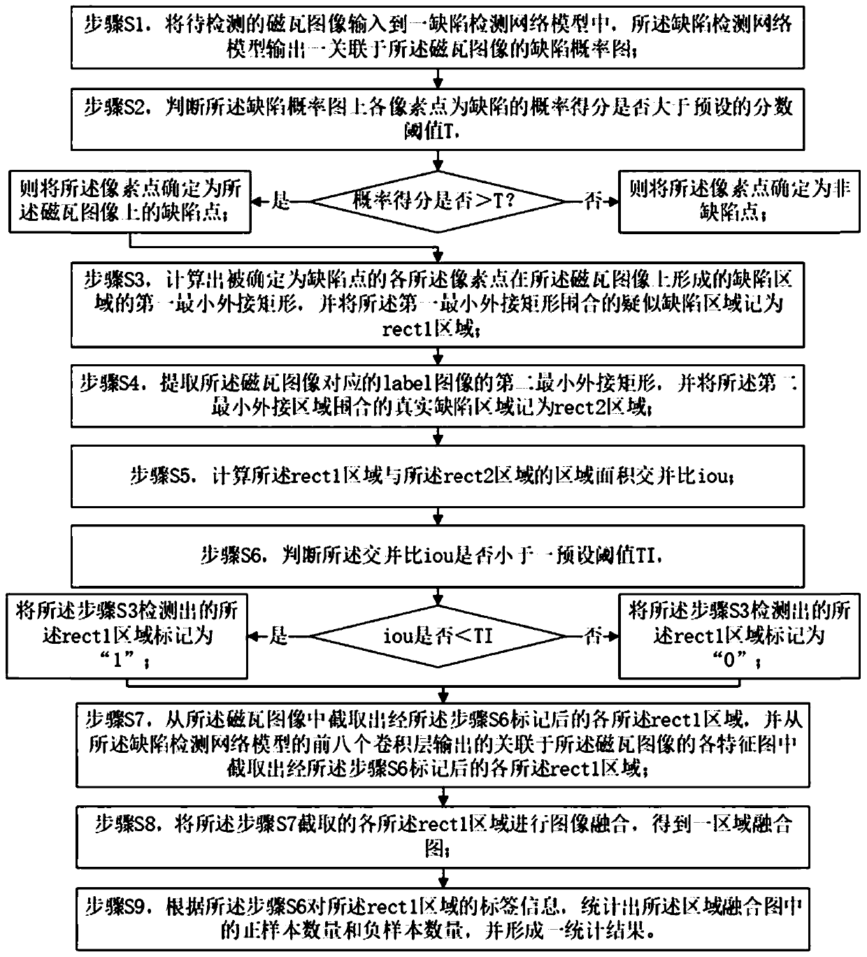
The invention discloses a magnetic shoe surface defect detection method. The method comprises the following steps of: inputting a magnetic shoe image into a defect detection network model, and outputting a defect probability graph; judging whether each pixel point on the defect probability graph is a defect point or not; extracting a suspected defect area enclosed by each defect point, and recording the suspected defect area as rect1; extracting a real defect area on the label image corresponding to the magnetic tile image, and recording the real defect area as rect2; calculating a regional area intersection ratio of the rect1 to the rect2; judging whether the prediction result of the model is correct or not according to the cross-parallel ratio, and marking the rect1 area as '1'or '0' according to the prediction result; intercepting each marked rect1 area from the magnetic shoe image and each feature map output by the model; and fusing the intercepted rect1 regions to obtain a area fusion graph. According to the method, the false detection rate of the magnetic shoe defects is reduced.

Description

technical field [0001] The invention relates to the field of defect detection and counting, in particular to a method for detecting defects on the surface of magnetic tiles. Background technique [0002] Magnetic tile is a ferrite tile-shaped permanent magnet material, the main components are iron oxide and strontium oxide, generally used in permanent magnet motors, and its function is to replace the magnetic field generated by the excitation winding. Magnetic tiles are the key components of permanent magnet motors, and the quality of magnetic tiles directly affects the quality of permanent magnet motors. [0003] Representative defects of magnetic tiles include cracks, ring cracks, drop corners, non-planar surfaces of magnetic tiles, etc. For the detection of magnetic tile defects, at present, major magnetic tile manufacturers generally adopt traditional manual detection methods. Manual detection has high labor costs, high labor intensity, and human eyes are prone to fatig...

Claims


Application Information

Patent Timeline
Patent Type & Authority Applications(China)
IPC IPC(8): G06T7/00G06T7/187G06T7/62G06N3/04
CPCG06T7/0004G06T7/187G06T7/62G06N3/045Y02P90/30
Inventor 张发恩郝磊刘强强刘旭
Owner 创新奇智(青岛)科技有限公司
Learn More