
Device and method for improving magnetostrictive guided wave detection sensitivity

A technology of detection sensitivity and magnetostriction, which can be used in measurement devices, analysis of solids using sonic/ultrasonic/infrasonic waves, and material analysis using sonic/ultrasonic/infrasonic waves, etc. Achieve defect detection without blind spots, low cost of equipment improvement, and increase the effect of sound wave attenuation

Inactive Publication Date: 2015-10-21
HUAZHONG UNIV OF SCI & TECH
View PDF9 Cites 4 Cited by
  • Summary
  • Abstract
  • Description
  • Claims
  • Application Information

AI Technical Summary

Problems solved by technology

[0004] However, the existing technology only optimizes the guided wave detection technology from the excitation or reception mode, and realizes defect detection based on the primary echo signal of the defect. At this time, the attenuation will not only reduce the sensitivity of defect detection, but also reduce When the value is not obvious or the defect is in the detection blind zone, it is easy to miss the defect detection

Method used


Image

  • Device and method for improving magnetostrictive guided wave detection sensitivity
  • Device and method for improving magnetostrictive guided wave detection sensitivity
  • Device and method for improving magnetostrictive guided wave detection sensitivity

Examples


Embodiment 1

[0052] The pipeline to be tested is figure 2 As shown, point a to point d is a section of the pipeline to be detected with a length of 2m. Install the signal enhancement components at both ends of the area to be detected respectively, the excitation sensor is installed at point a close to the signal enhancement component at the left end, and the receiving sensor is installed at point b, and the distance from the signal enhancement component at the left end is L 1 , and other components are also connected in sequence; the distance between the defect and the receiving sensor is L 2 , the distance from the signal enhancement element at the right end is L 3 , then the amplitude of the first defect echo signal D1 can be expressed as

[0053] A 1 = A 0 · R D · e - α ( ...

Embodiment 2

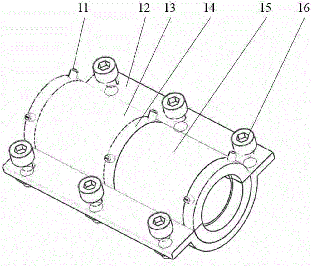
[0062] image 3 It is a structural schematic diagram of a signal enhancement element for a tubular or rod-shaped object to be detected, including: an attenuation module 13 , a reflection module 15 , a partition 14 , and a housing 12 .

[0063] Wherein, the reflection module 15, the partition 14 and the attenuation module 13 jointly constitute the inner layer of the signal enhancement element 1, which is fixed on the outer surface of the object 5 to be detected by the outer shell, the material of the reflection module 15 is steel, and the material of the attenuation module 13 is rubber.

[0064] The reflection module 15 and the attenuation module 13 are arranged on the outer surface of the object to be detected 5, and three pairs of partitions 14 are respectively arranged between the reflection module 15 and the attenuation module 13, and at both ends of the inner layer of the signal enhancement element.

[0065] The attenuation module 13, the reflection module 15, the casing ...

Embodiment 3

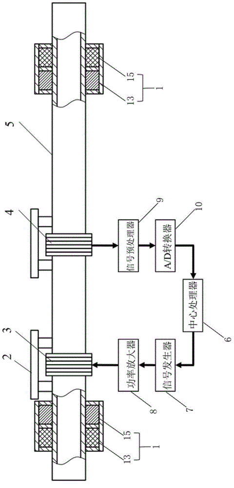
[0067] Figure 4 According to the working schematic diagram of the device for improving the detection sensitivity of magnetostrictive guided waves according to the present invention, the detection object 5 is 25mm in outer diameter, 20mm in inner diameter, and the length is L 1 = 2.8m steel pipe, 0.5mm deep transverse groove defect 17 distance L from the left end of the pipe 2 =0.8m, the equivalent cross-sectional area loss is about 14.4%. Set L from the left end of the pipe 3 A section of =1.2m is the detection area. The device is equipped with a signal enhancement element 1 in Embodiment 2 at the right end of the detection area. The internal diameter of this element is 24mm, and its reflection module 15 is installed near the sensor 3 (4). The detection steps are as follows:

[0068] (1) The central processor controls the signal generator to generate an excitation signal, which is input to the excitation sensor 3 through a power amplifier, and is excited to generate an ult...


PUM


Abstract

The invention discloses a device for improving the magnetostrictive guided wave detection sensitivity, and a method for improving the magnetostrictive guided wave detection sensitivity by using the same; a center processor controls a signal generator to generate an excitation signal, the excitation signal is inputted into an excitation sensor through a power amplifier, and an ultrasonic guided wave is excited at a to-be-detected area and is propagated in the axial direction; after reflection by signal enhancement components, the ultrasonic guided wave is superposed and enhanced, then inputted to a receiving sensor, inputted to an A / D converter through a signal preprocessor, and next is converted into a digital signal, and the digital signal is inputted to the center processor; the center processor analyzes the digital signal, and the position of a defect in the to-be-detected area is concluded. The signal enhancement component is introduced to a traditional magnetostrictive guided wave detection device, so that the defect multiple echo signal amplitude value is enhanced, the purpose of improving the guided wave detection sensitivity is achieved, at the same time, the conventional device has no need of complex modification, and non-blind area defect detection can be realized.

Description

technical field [0001] The invention belongs to the field of non-destructive testing, and more specifically relates to a device and method for improving the detection sensitivity of magnetostrictive guided waves. Background technique [0002] In petroleum, chemical, energy and other industries, pipes and pipelines are widely used, and after long-term use, failure forms such as corrosion, perforation or wall thickness reduction will occur. In order to avoid accidents, regular non-destructive testing of industrial pipelines is required. Ultrasonic guided wave detection technology has the advantage of realizing rapid detection of a section of area with single-point excitation, and is widely used in this field. [0003] The invention patent with application number 96193606.1 discloses a non-destructive inspection method for pipes and pipes using magnetostrictive sensors (the date of publication is May 27, 1998), and mainly introduces a method for inspecting ferromagnetic pipes ...

Claims


Application Information

Patent Timeline
Patent Type & Authority Applications(China)
IPC IPC(8): G01N29/22G01N29/32G01N29/07
Inventor 武新军从明
Owner HUAZHONG UNIV OF SCI & TECH
Learn More