
Oil coating device for tin electroplating treatment

An oil coating device and electro-tinning technology are applied to the surface coating liquid device, coating, cleaning method and utensils, etc., which can solve the problems of missing coating of workpieces, affecting the service life of workpieces, waste of anti-rust oil, etc., and achieve The effect of reducing waste, improving efficiency, and simplifying oiling work

Active Publication Date: 2020-05-05
南京天印电镀有限公司
View PDF19 Cites 0 Cited by
  • Summary
  • Abstract
  • Description
  • Claims
  • Application Information

AI Technical Summary

Problems solved by technology

[0004] Although the electroplating tin solutions are different, the electroplating process is basically the same. The basic process is divided into pretreatment, electroplating, reflow, passivation and antirust oil coating; Due to the special shape of the pot-shaped workpiece when using rust oil, a large amount of anti-rust oil will be brought out after being directly immersed in the anti-rust oil, resulting in a waste of anti-rust oil, and it is necessary to manually immerse the workpiece in the anti-rust oil, which may easily cause leakage of the workpiece. Coated, thus affecting the service life of the workpiece,

Method used


Image

  • Oil coating device for tin electroplating treatment
  • Oil coating device for tin electroplating treatment
  • Oil coating device for tin electroplating treatment

Examples


specific Embodiment approach

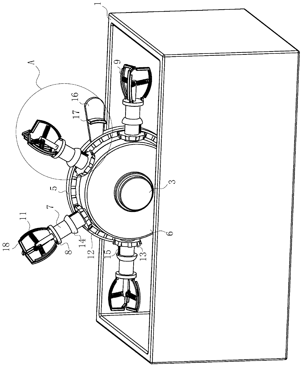
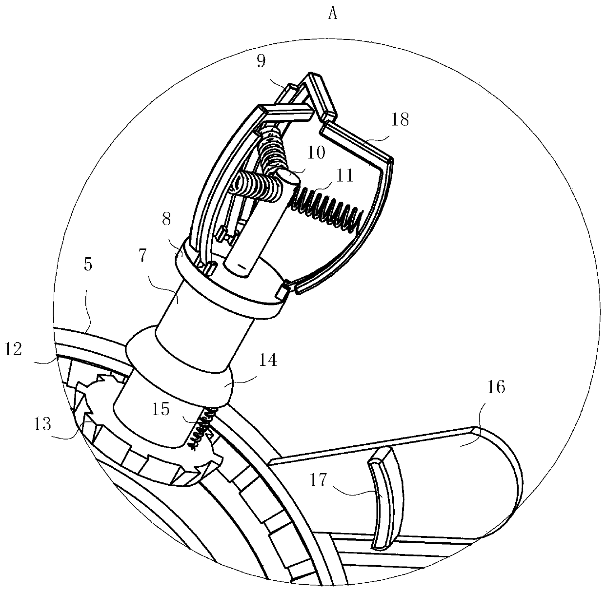
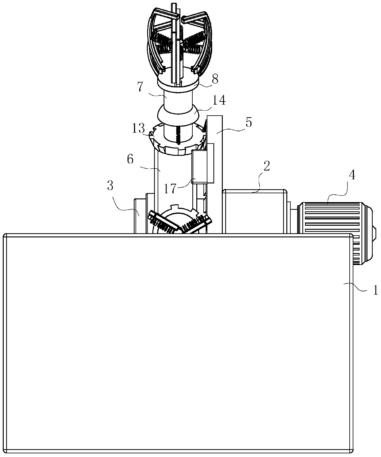
[0032] As a specific embodiment of the present invention, a No. 1 helical gear 12 is fixed on the side of the No. 1 plate 5 away from the drive motor 4, and a No. 2 helical gear 13 is fixed on the end of the connecting rod 7 close to the No. 2 disc 6. The No. 2 helical gear 13 meshes with the No. 1 helical gear 12. During work, the contact between the gripper 9 and the workpiece will easily cause the contact part of the workpiece and the gripper 9 to be difficult to contact the anti-rust oil, thereby causing the missing coating of the workpiece; The setting of the helical gear 12 and the second helical gear 13 makes the connecting rod 7 drive the second helical gear 13 to rotate during the rotation, so that the second helical gear 13 and the first helical gear 12 are relatively displaced; the rotating second helical gear The gear 13 rotates during the relative displacement with the No. 1 helical gear 12, so that the connecting rod 7 rotates, so that the gripper 9 rotates around...


PUM


Abstract

The invention belongs to the technical field of tin electroplating oil coating treatment, and particularly relates to an oil coating device for tin electroplating treatment. The device comprises an oil pool, wherein a mounting plate is fixed in an inner cavity of the oil pool, a rotating shaft is rotatably arranged on the side wall of the mounting plate, the rotating shaft penetrates through the mounting plate, an output shaft of a driving motor is fixedly connected with the rotating shaft, a first disc is fixed on the side, away from the driving motor, of the mounting plate, a second disc isrotatably connected with the end, away from the first disc, of the rotating shaft, connecting rods are rotatably arranged on the side wall of the second disc in the circumferential direction of the second disc at equal distances, and a mounting disc is fixed on the end, away from the second disc, of each connecting rod. According to the device, an electric push rod is controlled to contract by a controller, the electric push rod drives a connected sliding seat to move in a direction close to the mounting disc, and the sliding seat pulls and holds a connected first spring, so that a connected gripping hand synchronously contracts towards the middle part, then the outer diameter of the gripping hand is reduced, the gripping hand can easily enter a workpiece, and the gripping hand can conveniently and quickly enter the workpiece.

Description

technical field [0001] The invention belongs to the technical field of electroplating tin oiling treatment, in particular to an oiling device for electroplating tin treatment. Background technique [0002] Tin coating has been widely used in the electronics industry as a protective and solderable coating for electronic components, wires, printed circuit boards and integrated circuit blocks due to its excellent corrosion resistance and solderability. [0003] The application of electroplating tin is very extensive. Tin has the advantages of corrosion resistance, discoloration resistance, non-toxicity, easy brazing, softness, low melting point and good ductility. Dense, uniform and continuous alloy coating. [0004] Although the electroplating tin solutions are different, the electroplating process is basically the same. The basic process is divided into pretreatment, electroplating, reflow, passivation and antirust oil coating; Due to the special shape of the pot-shaped wor...

Claims


Application Information

Patent Timeline
Patent Type & Authority Applications(China)
IPC IPC(8): B05C3/10B05C9/10B05C13/02B08B1/04B08B13/00
CPCB05C3/10B05C13/02B05C9/10B08B13/00B08B1/143B08B1/32
Inventor 鲍合祥韩涛
Owner 南京天印电镀有限公司
Learn More