
In-vitro simulation circulatory system for artificial heart test

An artificial heart and in vitro simulation technology, applied in the direction of heart valves, can solve problems such as difficult to simulate myocardium, and achieve the effect of optimizing fluid mechanical properties

Pending Publication Date: 2020-05-01
TSINGHUA UNIV
View PDF0 Cites 6 Cited by
  • Summary
  • Abstract
  • Description
  • Claims
  • Application Information

AI Technical Summary

Problems solved by technology

In the actual beating process of the heart, it is divided into four stages: isovolumic contraction, ejection, isovolumic relaxation, and filling. The existing simulated circulatory systems at home and abroad are difficult to simulate the Frank-Starling mechanism of myocardial contraction and relaxation, that is, before and after the heart. Mechanisms for passive regulation of pulsatile state during load changes

Method used


Image

  • In-vitro simulation circulatory system for artificial heart test
  • In-vitro simulation circulatory system for artificial heart test
  • In-vitro simulation circulatory system for artificial heart test

Examples


Embodiment 1

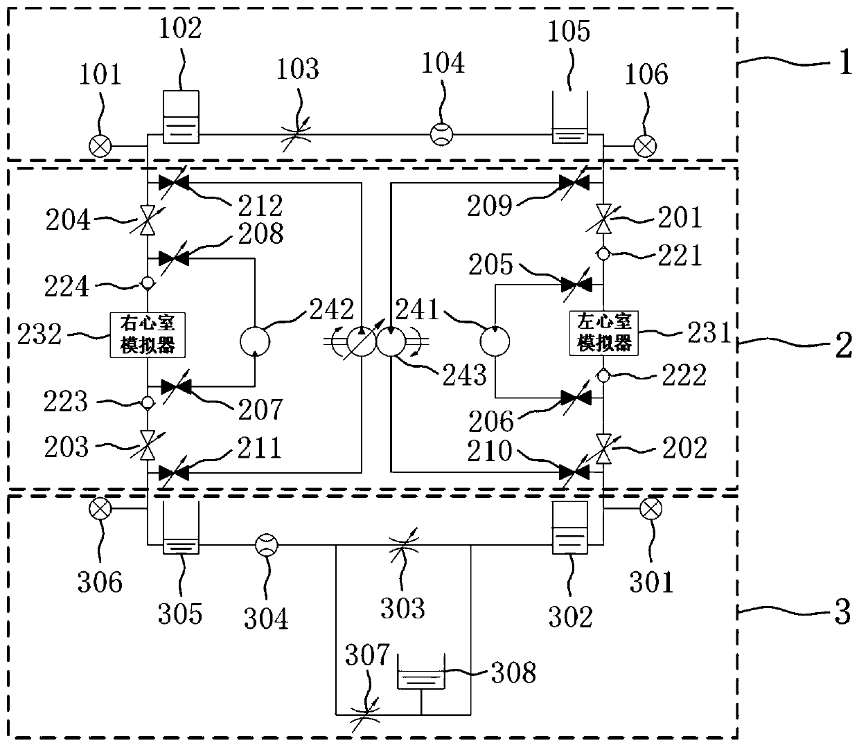
[0047] In this example, if image 3 As shown, before inserting the artificial heart assist device for testing, it is first necessary to accurately simulate the patient's blood flow state. Open the first to fourth gate valves (201, 202, 203, 204), and close the fifth to twelfth gate valves (205, 206, 207, 208, 209, 210, 211, 212). According to the required heartbeat state, such as exercise, rest, heart failure, etc., adjust the volume pre-pressure of the sealed gas in the first sealed container 102 to simulate the compliance of the pulmonary artery, and adjust the liquid level in the first open container 105 to simulate the pulmonary vein. For compliance, adjusting the first throttle valve 103 simulates pulmonary circulation vascular resistance. Adjust the volume pre-pressure of the sealing gas in the second sealed container 302 to simulate the compliance of the aorta, adjust the liquid level in the second open container 305 to simulate the compliance of the main vein, adjust ...

Embodiment 2

[0055] Such as Figure 9 As shown, taking the left ventricle simulator 231 as an example, it includes: a linear motor 42 , a flexible connector 41 , and a piston cylinder 43 . In the present invention, the left and right ventricle simulators (231, 232) automatically respond to changes in front and rear loads through the flexible connector 41. The structure of the flexible connector 41 is as follows: Figure 10 As shown, it includes: an elastic element 411 , a diastolic limiter 412 , a contraction limiter 413 , a linear motor connector 414 , and a piston-cylinder connector 415 . The stroke of the linear motor 42 is a fixed value when simulating the process of ventricular contraction and diastole, then when filling, the stroke of the motor is equal to the sum of the elongation of the elastic element 411 and the stroke of the piston during the filling period; when ejecting blood, the stroke of the motor is equal to the stroke of the elastic element 411 The sum of the compression...


PUM


Abstract

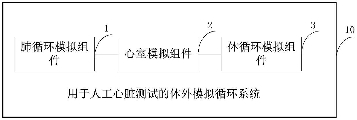
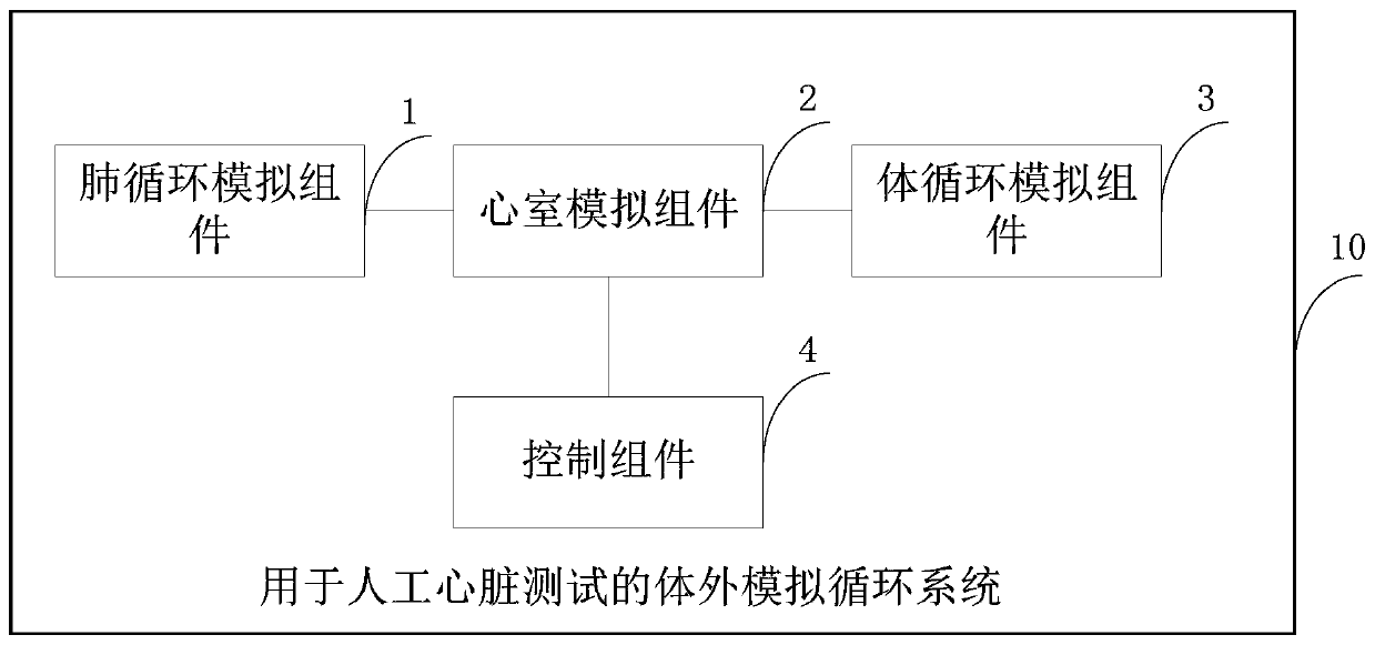
The invention discloses an in-vitro simulation circulatory system for artificial heart test. The system comprises a ventricle simulation module, a lung circulation simulation module and a systemic circulation simulation module, and realizes the simulations of the blood flowing state and the organ perfusion state of a human body. In a left ventricle simulator and a right ventricle simulator, cardiac muscles are simulated through flexible connectors, myocardial contraction and relaxation are simulated by using elastic components, and limit state of the myocardial contraction and relaxation is simulated by using limiters, thus realizing a passive regulation of ventricular beating state during changes in cardiac preload and afterload. Meanwhile, by simulating different blood flow paths and different organ perfusion levels, the invention can be used to test and optimize various types of artificial heart (ventricle assist pump) devices, and to objectively test and optimize hydrodynamic performance of products.

Description

technical field [0001] The invention relates to the technical field of medical instrument detection, in particular to an in vitro simulated circulatory system for artificial heart testing. Background technique [0002] Heart failure is the final outcome of various cardiovascular diseases. At present, there are at least 10 million heart failure patients in China. The prognosis of patients is poor and the mortality rate is high. The mortality rate within 5 years is as high as 60%. Heart transplantation is the first choice for the treatment of end-stage heart failure, but limited by the shortage of donors, only a few hundred heart transplants are performed in China every year. Therefore, the use of artificial hearts to temporarily or permanently replace heart transplantation is a very promising development direction. [0003] At present, artificial hearts are divided into left ventricular assist device (LVAD), right ventricular assist device (RVAD), biventricular assist device...

Claims


Application Information

Patent Timeline
IPC IPC(8): A61F2/24
CPCA61F2/2472
Inventor 张宇赵翔栗桂玲
Owner TSINGHUA UNIV
Learn More