Energy recovering flow control valves

A technology for controlling valves and fluid flow, which is applied in the direction of valve energy absorption devices, valve lifts, valve details, etc. It can solve the problems of local velocity increase, fluid average velocity decrease, and supply, etc., to reduce local velocity Peaking, reduced risk of cavitation, easy-to-manufacture effects

Active Publication Date: 2017-12-01
米兰综合工科大学
View PDF8 Cites 3 Cited by
  • Summary
  • Abstract
  • Description
  • Claims
  • Application Information

AI Technical Summary

Problems solved by technology

[0009] However, this known valve suffers from the disadvantage that said known valve induces a significant local energy loss when the obturator is partially closed to regulate the fluid flow; this loss leads to a reduction in the average velocity of the fluid and thus to a flow rate decrease, or cause the flow rate to be the same while the pressure differential between the upstream and downstream sides of the valve changes, but they generally do not provide any energy advantage to the system that includes the valve
[0010] Moreover, such known valves cause a sudden change in section along the path followed by the fluid, causing a local velocity increase and thus a sudden drop in pressure, in particular when the obturator is in a partially closed position for regulating the fluid flow, This can cause undesired and harmful cavitation problems that can prevent proper valve operation

Method used


Image

  • Energy recovering flow control valves
  • Energy recovering flow control valves
  • Energy recovering flow control valves

Examples


Embodiment Construction

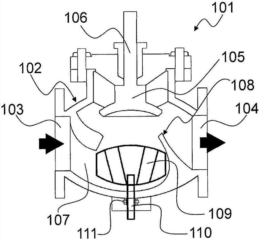
[0044] figure 1 A schematic diagram of one embodiment of a control valve 101 is shown, which is of the "ball" type.

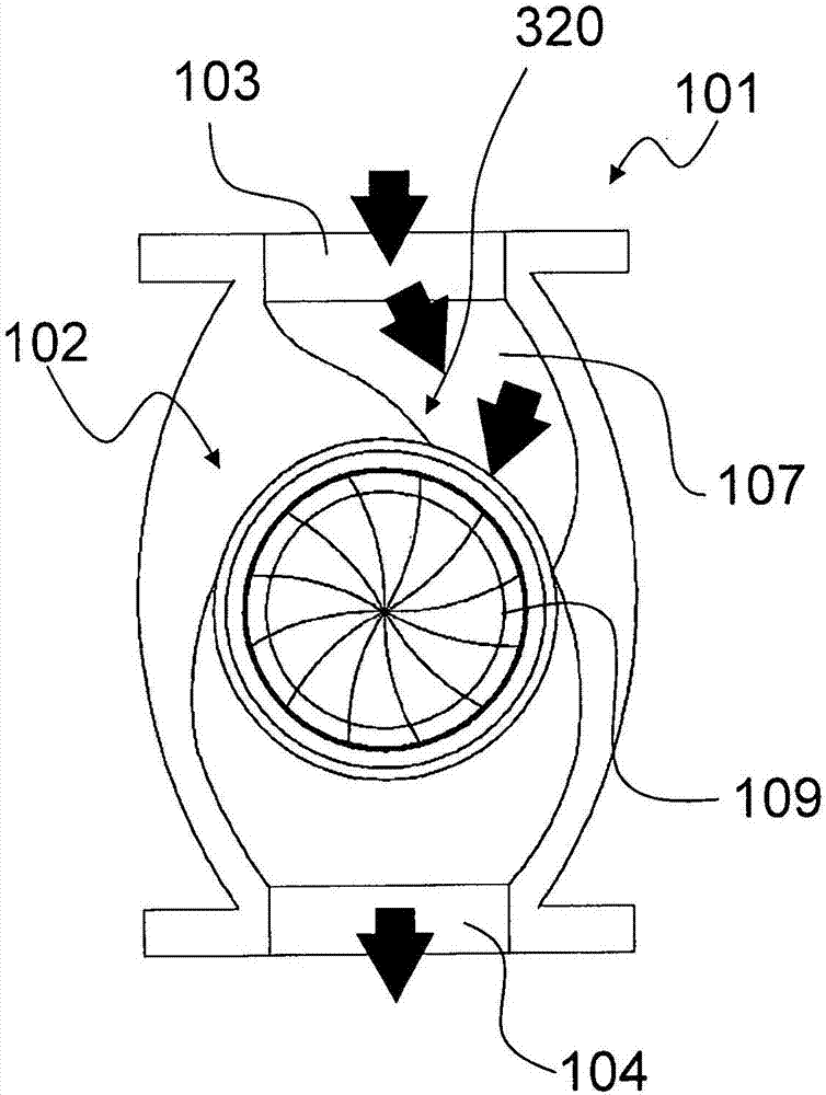
[0045]Valve 101 includes a valve body 102 having an inlet 103 and an outlet 104 that allow fluid to flow through valve 101 in the direction indicated by the thick arrow.

[0046] In operating conditions, the valve 101 may be mounted to the piping of the pressurized system. Valve 101 also includes an occluder 105 inserted into valve body 102, and an actuation rod 106 configured to reversibly translate occluder 105 within the valve body.

[0047] In the illustrated embodiment, the actuating rod 106 may be manually operated, for example by means of a screw-type mechanism and a knob (not shown); however, other solutions are possible for the actuator system. Possible, for example mechanical or pneumatic or hydraulic or electric or electromechanical.

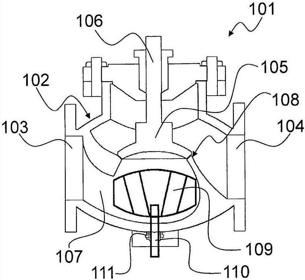
[0048] The occluder 105 is configured to be in the first position (see figure 1 ) and a second position in which...


PUM


Abstract

A control valve for a fluid flow, comprising: a valve body (102, 402, 602, 802, 1002) that defines an inlet (103, 403, 603, 803, 1003) and an outlet (104, 404, 604, 804, 1004) for the fluid, an obstructer (105, 405, 605, 805, 1005) inserted in the valve body (102, 402, 602, 802, 1002), and an actuator system (106, 406, 606, 806, 1006) configured for reversibly translating the obstructer (105, 405, 605, 805, 1005) between a first position, in which the obstructer (105, 405, 605, 805, 1005) allows the passage of the fluid between said inlet (103, 403, 603, 803, 1003) and the outlet (104, 404, 604, 804, 1004), and a second position, in which the obstructer (105, 405, 605, 805, 1005) prevents the passage of the fluid between the inlet (103, 403, 603, 803, 1003) and the outlet (104, 404, 604, 804, 1004); the control valve further comprises a turbine rotor (109, 409, 609, 809, 1009) housed inside the valve body (102, 402, 602, 802, 1002), wherein the rotor (109, 409, 609, 809, 1009) comprises a plurality of blades and is configured for continuously rotating under the action of the fluid flowing between the inlet (103, 403, 603, 803, 1003) and the outlet (104, 404, 604, 804, 1004), the rotor (109, 409, 609, 809, 1009) rotating about an axis of rotation substantially aligned with the direction of translation of the obstructer (105, 405, 605, 805, 1005).

Description

technical field [0001] The present invention relates to a fluid flow control valve, in particular a control valve that allows recovery of a portion of the energy of the fluid flowing through the valve itself. Background technique [0002] Devices are known to control the flow of fluid through pipes, said devices being referred to as "valves". Valves are commonly used as on / off and regulating devices in pipelines for fluids, especially fluids under pressure. A valve allows a pipe connected to it to be selectively closed to prevent the flow of a fluid (such as a gas, liquid, vapor, or two-phase fluid) therethrough. [0003] Among the various valves known in the prior art are control valves known as "ball" valves and control valves known as "needle" valves. [0004] A "ball" control valve includes a valve body and an obturator inserted into the valve body that is translatable within the valve body to a position that blocks the passage of fluid from the inlet cavity. The obtu...

Claims


Application Information

Patent Timeline
IPC IPC(8): F16K47/08F16K1/00
CPCF01D15/00F01D15/12F03B13/00F16K1/00F16K47/08F01D1/04F01D1/06F01D17/145F05D2260/4031F05D2260/404F16K1/12F16K31/50
Inventor S·马拉瓦西
Owner 米兰综合工科大学
Why Eureka
Try Eureka