
Main shaft and workpiece vibration prediction method based on stack sparse automatic coding network

A technology of sparse automatic coding and prediction method, which is applied in the field of spindle and workpiece vibration prediction based on stacked sparse automatic coding network, can solve the problems of complex analysis and calculation process and the influence of missing frequency response, so as to improve processing efficiency, save cost, Improvement of machining accuracy and surface quality

Active Publication Date: 2020-04-28
HUAZHONG UNIV OF SCI & TECH
View PDF4 Cites 8 Cited by
  • Summary
  • Abstract
  • Description
  • Claims
  • Application Information

AI Technical Summary

Problems solved by technology

Although these two methods can reflect some characteristics of the dynamic frequency response to a certain extent, they each have their own shortcomings. The analysis and calculation process of the former is very complicated, and the latter directly loses the influence of the dynamic cutting process on the frequency response.

Method used


Image

  • Main shaft and workpiece vibration prediction method based on stack sparse automatic coding network
  • Main shaft and workpiece vibration prediction method based on stack sparse automatic coding network
  • Main shaft and workpiece vibration prediction method based on stack sparse automatic coding network

Examples


specific Embodiment

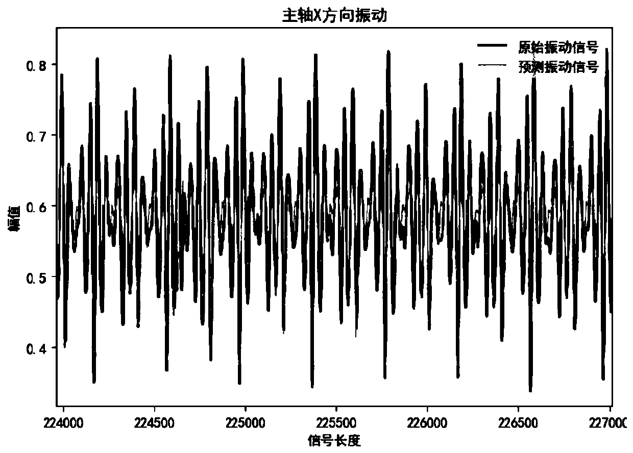
[0070] As used in this example Figure 6 For the thin-walled part shown, the cutting experiment is carried out to obtain relevant parameters, and the prediction model is obtained by training according to the above method, and then the input data in the test set are input into the prediction model. The prediction results are as follows: Figure 3(a) ~ Figure 3(f) As shown, the fitting effect of the spindle vibration in the x direction, y direction, and z direction and the workpiece vibration in the y direction and z direction is better (the tool feed direction is the x direction, and the vertical direction is the z direction), which can be more accurate Reflect the vibration situation and trend of the spindle and workpiece during the cutting process; such as Figure 4(a) ~ Figure 4(f) It can be seen that the predicted results of the predicted data in the selected frequency band are very similar to the frequency distribution of the actual data in this frequency band, which can m...


PUM


Abstract

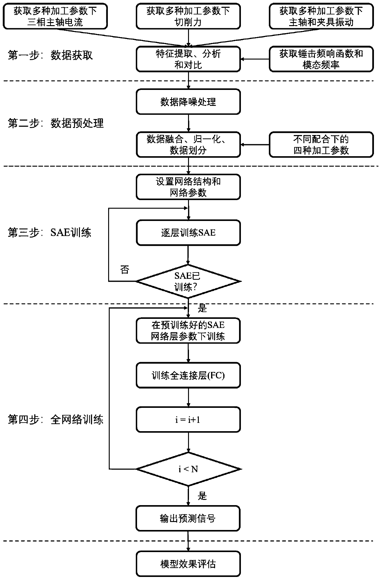
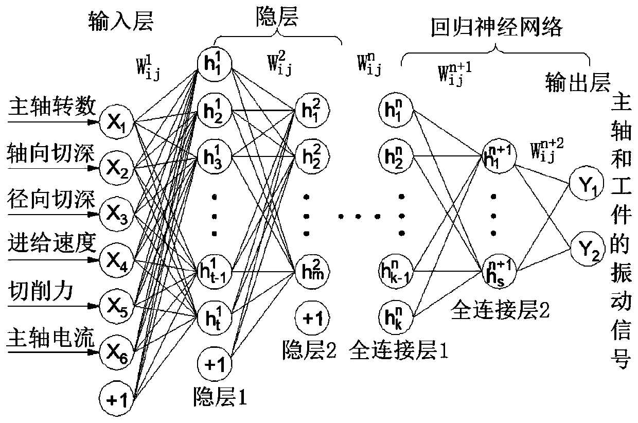
The invention belongs to the field of cutting processing, and particularly discloses a main shaft and workpiece vibration prediction method based on a stack sparse automatic coding network, which comprises the following steps: S1, obtaining main shaft current signals, cutting force signals and main shaft and workpiece actual vibration signals under different cutting processing parameters; S2, inputting the main shaft current signal, the cutting force signal and the cutting machining parameter into a sparse automatic coding network layer for training to obtain a deep time sequence characteristic, inputting the deep time sequence characteristic into a full connection layer, and training the whole network on the basis of a pre-training parameter to obtain a main shaft and workpiece predictionvibration signal; S3, adjusting the stack sparse automatic coding network according to the main shaft and workpiece prediction and actual vibration signals, and completing training to obtain a prediction model; main shaft and workpiece vibration signal prediction in cutting machining is achieved through the prediction model, a dynamic frequency response function can be replaced, a good predictioneffect is achieved in the time domain and the frequency domain, the prediction model can adapt to working conditions of various machining parameter combinations, and the generalization capacity is high.

Description

technical field [0001] The invention belongs to the field of cutting processing, and more specifically relates to a method for predicting the vibration of a spindle and a workpiece based on a stacked sparse auto-encoding network. Background technique [0002] Today, the manufacturing industry is moving forward from digitization and informatization to intelligence. The monitoring of the manufacturing process is the core of intelligent manufacturing. How to effectively monitor the processing status is the core area of ​​research and development that countries around the world are committed to. [0003] During the cutting process, it is very difficult to obtain the dynamic frequency response function of a certain subsystem of the machining system. Most of the existing research methods are mathematical analysis methods, or the static response function of the subsystem is obtained through hammering experiments. The static response function approximates the dynamic response functi...

Claims


Application Information

Patent Timeline
Patent Type & Authority Applications(China)
IPC IPC(8): G06K9/00G06K9/62G01M7/02
CPCG01M7/02G06F2218/04G06F2218/08G06F18/214
Inventor 刘红奇
Owner HUAZHONG UNIV OF SCI & TECH
Learn More