Fiber separator

The technology of a fiber separator and a tank body is applied in the field of papermaking, which can solve the problems of large pressure difference at the bottom of the sieve plate, large deformation force of the sieve plate, mixed pulp, etc., and achieve the effect of good decoupling and separation

Active Publication Date: 2020-04-28
山东建丰纸业有限公司
View PDF8 Cites 0 Cited by
  • Summary
  • Abstract
  • Description
  • Claims
  • Application Information

AI Technical Summary

Problems solved by technology

[0003] 1. When the impeller rotates to drive the waste paper pulp to rotate, when the feed speed becomes faster, the impurity content will increase, and its decompression effect will drop a lot. When the decompression effect will cause some paper materials in a lot of waste paper pulp If the sieve plate is not completely dislodged, it will block the sieve plate, which will not only cause great damage to the sieve plate, but also affect the filtration effect and affect the overall separation efficiency.
[0004] 2. The filtering of the sieve plate is fixed, and the position of the pulp outlet is set at the bottom, so that the filtration speed at the bottom of the sieve plate is fast due to the flow rate of the pulp outlet and the pressure difference during filtration, and then The probability of blockage at the bottom of the sieve plate is higher; and the pressure at the bottom of the sieve plate on the side to be filtered is high, and the pressure at the bottom of the slurry outlet side is much reduced due to the flow rate, which will cause the pressure difference at the bottom of the sieve plate to be too high. When the bottom of the sieve plate is deformed, the waste paper pulp will enter the pulp outlet and the pulp will be mixed, making the equipment unusable; at the same time, some long strips of pulp will flow out of the sieve plate hole. Enter the pulp tank and discharge, so that the produced paper will have strip marks, which is not conducive to use

Method used


Image

  • Fiber separator
  • Fiber separator
  • Fiber separator

Examples


Embodiment Construction

[0027] The following will clearly and completely describe the technical solutions in the embodiments of the present invention with reference to the accompanying drawings in the embodiments of the present invention. Obviously, the described embodiments are only some, not all, embodiments of the present invention. Based on the embodiments of the present invention, all other embodiments obtained by persons of ordinary skill in the art without making creative efforts belong to the protection scope of the present invention.

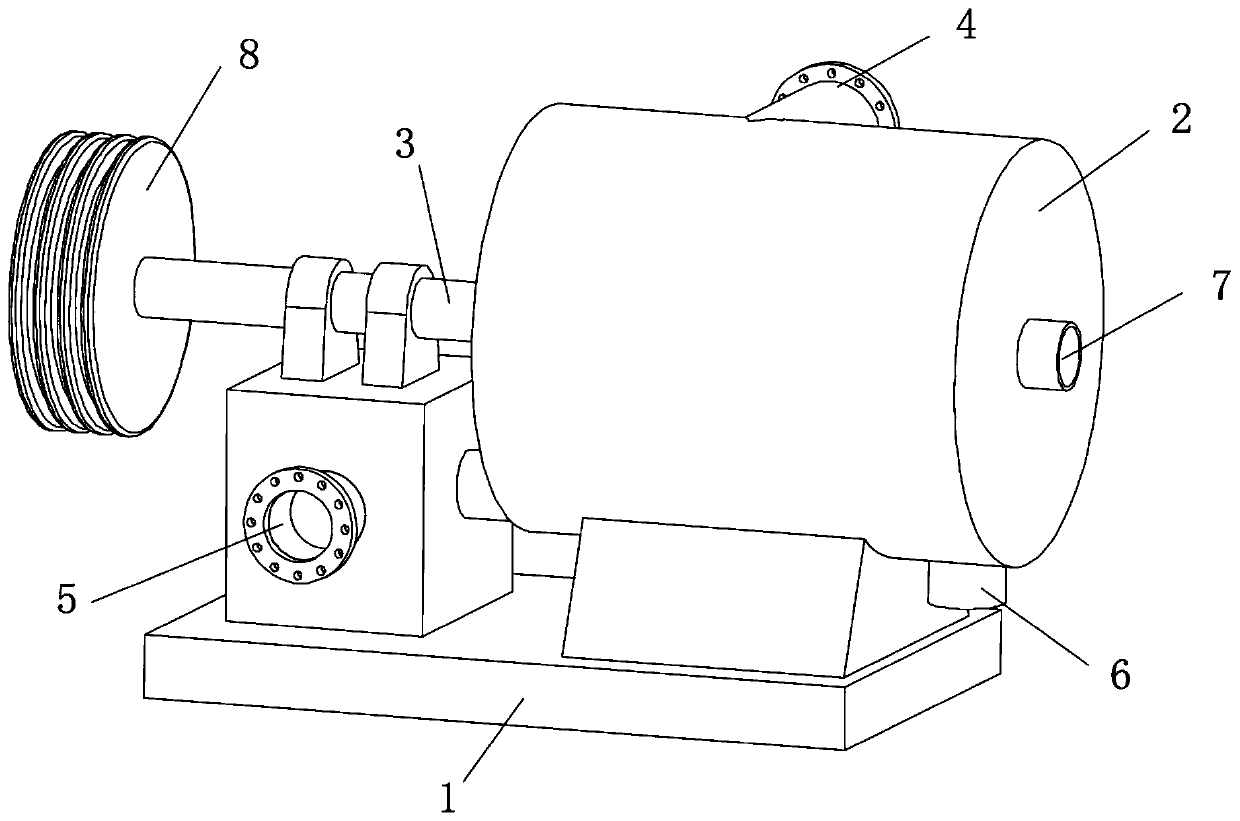
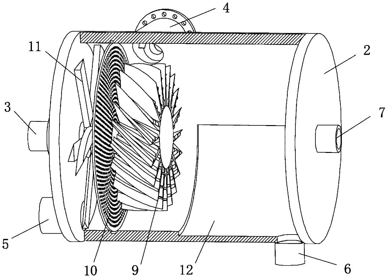
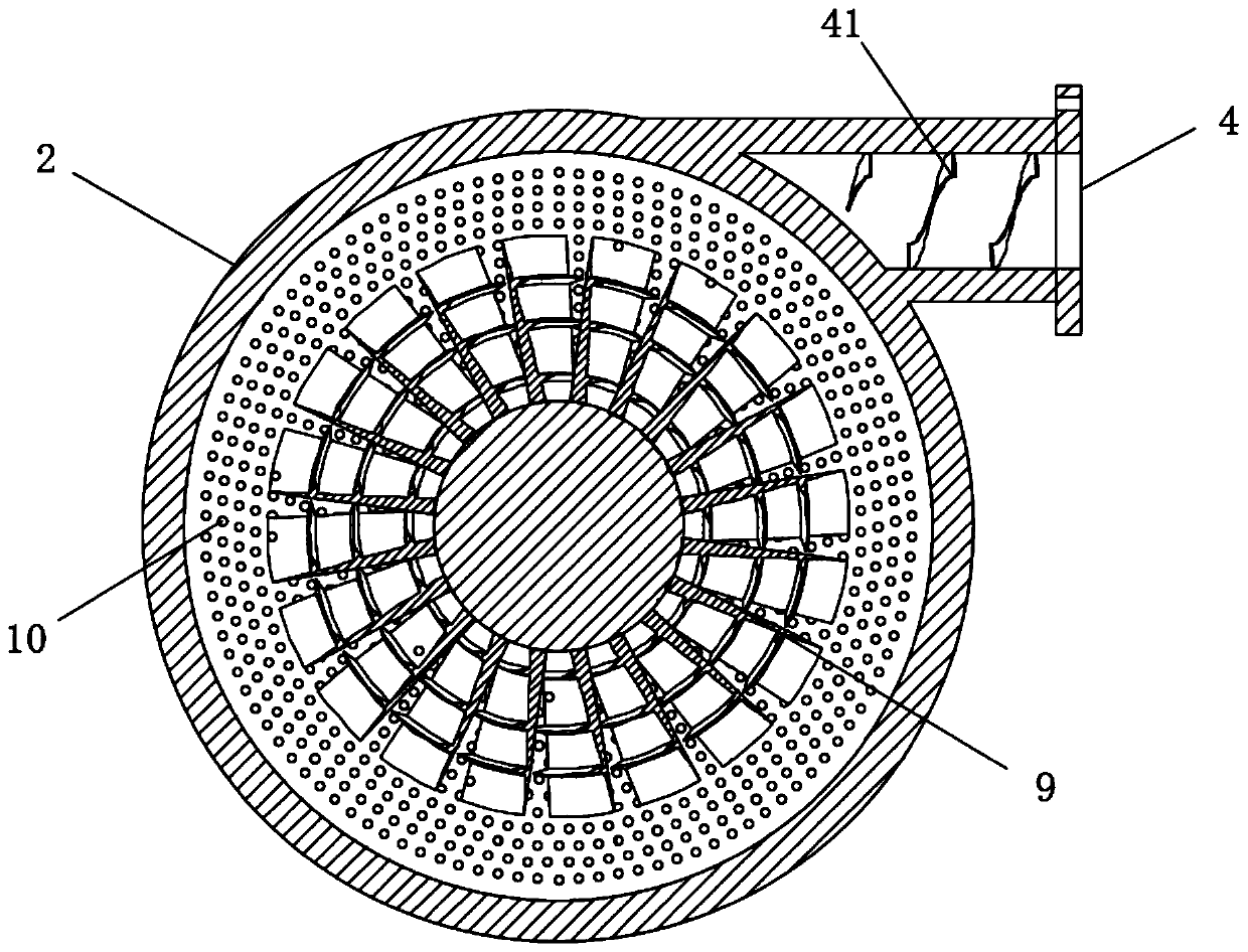
[0028] see Figure 1-8 , a fiber separator, comprising a base 1, a tank body 2 is fixedly installed on the front of the top of the base 1, a rotating shaft 3 is fixedly installed in the middle of the back of the tank body 2, and the rotating shaft 3 extends into the inside of the tank body 2, and the tank body 2 The top is tangentially provided with a pulp inlet 4, the bottom of the back of the tank body 2 is provided with a pulp outlet 5, the bottom of the ta...


PUM


Abstract

The invention relates to the technical field of papermaking, and discloses a fiber separator. The fiber separator includes a base, wherein a tank body is fixedly mounted on the front of the top of thebase; a rotating shaft is fixedly mounted in the middle of the back surface of the tank body and extends into the tank body; a slurry inlet is tangentially formed in the top of the tank body; a slurry outlet is formed in the bottom of the back of the tank body; a heavy impurity outlet is formed in the bottom of the tank body; a light impurity outlet is formed in the center of the front surface ofthe tank body; a belt wheel is fixedly installed at the end of the rotating shaft; the end, located in the tank body, of the rotating shaft is movably sleeved with an impeller; a sieve plate structure is movably installed at the position, located on the back surface of the impeller and in the tank body, of the rotating shaft; and a shearing device is arranged at the position, between the sieve plate structure and the back surface in the tank body, of the rotating shaft. According to the fiber separator, by improving the structures of the impeller and the sieve plate, the effect of defiberingand separating waste paper pulp is improved, and the service lifetime of the sieve plate is prolonged.

Description

technical field [0001] The invention relates to the technical field of papermaking, in particular to a fiber separator. Background technique [0002] Fiber separator is a kind of waste paper processing equipment. It uses the difference in specific gravity between waste paper pulp and light and heavy impurities to remove light and heavy impurities in waste paper raw materials. The light impurities are discharged from the light outlet in the middle of the gathering body, and the heavy impurities will rotate along the inner wall of the machine and finally fall to the bottom to be discharged from the heavy outlet. At the same time, the pulp filtered by the sieve plate is discharged from the pulp outlet. There are still some problems with the separator: [0003] 1. When the impeller rotates to drive the waste paper pulp to rotate, when the feed speed becomes faster, the impurity content will increase, and its decompression effect will drop a lot. When the decompression effect wi...

Claims


Application Information

Patent Timeline
Patent Type & Authority Applications(China)
IPC IPC(8): D21B1/32
CPCD21B1/32Y02W30/64
Inventor 刘其奎
Owner 山东建丰纸业有限公司
Why Eureka
Try Eureka