
Material sucking device and filling equipment

A material suction device and filling equipment technology, applied in the field of optical cable manufacturing, can solve the problems of lack of material or insufficient supply, affecting the water blocking effect of the product, and breaking the material, so as to achieve the effect of ensuring the water blocking effect.

Pending Publication Date: 2020-04-28
GUANGDONG HENGTONG PHOTOELECTRIC SCI & TECH +1
View PDF0 Cites 0 Cited by
  • Summary
  • Abstract
  • Description
  • Claims
  • Application Information

AI Technical Summary

Problems solved by technology

[0003] The existing process method manually adds the water blocking powder into the funnel, and then injects the water blocking powder into the corrugated steel strip through the funnel, so that the water blocking powder is tightly stuck on the outer surface of the bundle tube and the inner surface of the corrugated steel strip; Material breakage, material shortage or insufficient material supply lead to non-blocking water powder or discontinuous distribution of water-blocking powder in the corrugated steel strip, which affects the water-blocking effect of the product. At the same time, there is a micro gap between the bundle tube and the corrugated steel strip. There is relative sliding between the tube and the corrugated steel strip, which affects the attenuation and mechanical properties of the optical cable

Method used


Image

  • Material sucking device and filling equipment
  • Material sucking device and filling equipment
  • Material sucking device and filling equipment

Examples


Embodiment Construction

[0029] In order to make the purpose, technical solutions and advantages of the embodiments of the present invention clearer, the technical solutions in the embodiments of the present invention will be clearly and completely described below in conjunction with the drawings in the embodiments of the present invention. Obviously, the described embodiments It is a part of embodiments of the present invention, but not all embodiments. The components of the embodiments of the invention generally described and illustrated in the figures herein may be arranged and designed in a variety of different configurations.

[0030] Accordingly, the following detailed description of the embodiments of the invention provided in the accompanying drawings is not intended to limit the scope of the claimed invention, but merely represents selected embodiments of the invention. Based on the embodiments of the present invention, all other embodiments obtained by persons of ordinary skill in the art wi...


PUM


Abstract

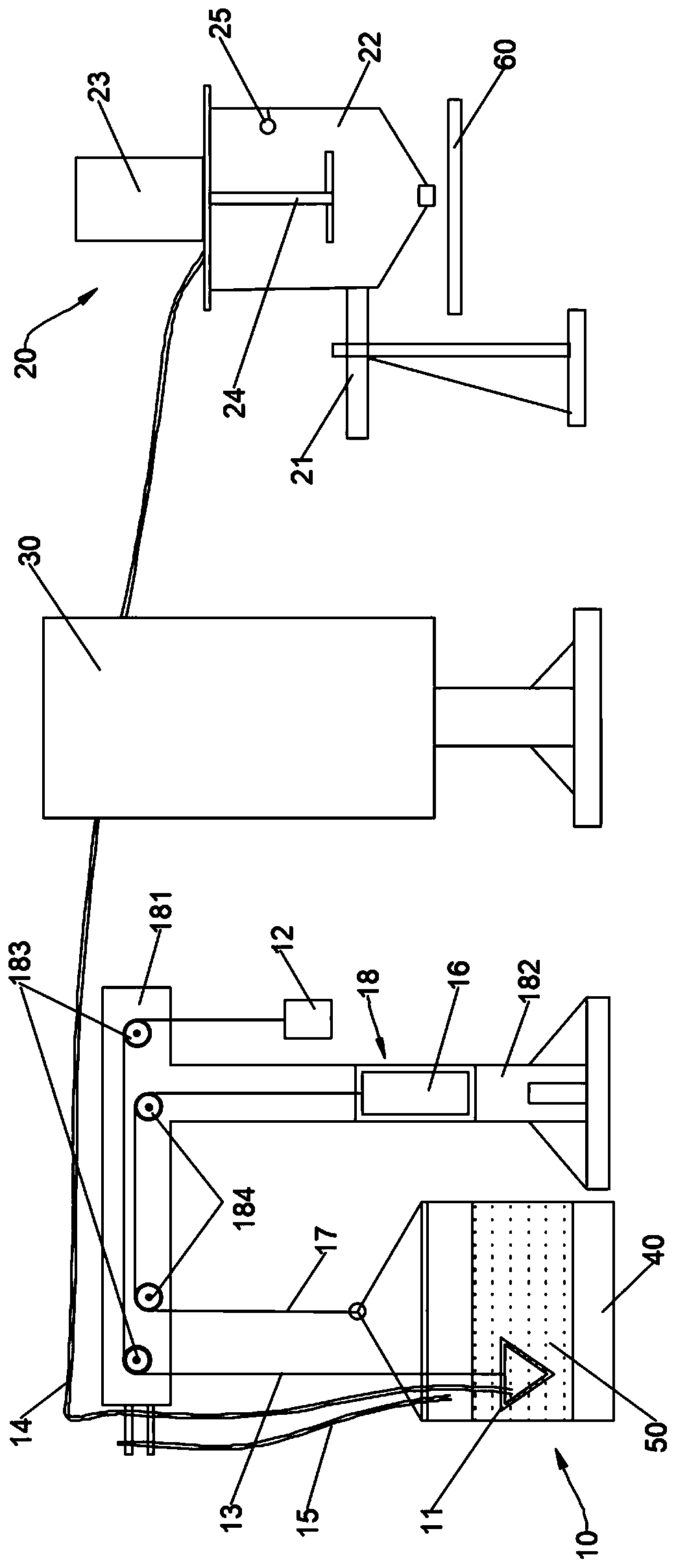
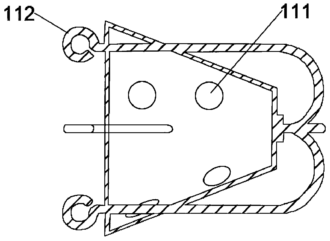
The invention discloses a material sucking device and filling equipment, and belongs to the technical field of optical cable manufacturing. The material sucking device is used for sucking a material in a packaging bag into a material filling device and comprises a material sucking head and a balancing weight, wherein the material sucking head is of a hollow structure with the side wall being provided with through holes, is arranged in the material in the packaging bag in a buried mode and communicates with the material filling device through a material sucking pipe, and the balancing weight and the material sucking head are connected through a first rope. The filling equipment comprises the material filling device and the material sucking device. The material sucking head is arranged in the material in the buried mode and balanced through the balancing weight, thus the material sucking head can automatically sink along with continuous reducing of the material in the packaging bag to ensure continuous material supplying to the material filling device, and the phenomenon of material discontinuing is avoided.

Description

technical field [0001] The invention relates to the technical field of optical cable manufacturing, in particular to a material suction device and filling equipment. Background technique [0002] For the central bundle tube optical cable, the longitudinal wrapping structure of water-blocking powder and corrugated steel strip can not only reduce the manufacturing cost of the cable, but also significantly improve the water-blocking effect. When water seeps in, the water-blocking powder can expand to the original Ten times to dozens of times, it blocks the water seepage channel, stops the further diffusion and extension of water or water vapor, and effectively protects the optical cable in the center. [0003] The existing process method manually adds the water blocking powder into the funnel, and then injects the water blocking powder into the corrugated steel strip through the funnel, so that the water blocking powder is tightly stuck on the outer surface of the bundle tube a...

Claims


Application Information

Patent Timeline
Patent Type & Authority Applications(China)
IPC IPC(8): B65B1/16
CPCB65B1/16
Inventor 曾辉李建宁胡珍王倩倩黄明书李曼曼郑美玲
Owner GUANGDONG HENGTONG PHOTOELECTRIC SCI & TECH
Learn More