
Die destruction device

A mold and equipment technology, applied in the field of mold destruction equipment, can solve the problems of customers' economic losses, different destruction methods, leakage of design patterns and core technologies, etc., and achieve the effects of convenient use, improved recycling rate, and simple structure

Inactive Publication Date: 2020-04-28
嵊州月明模具科技有限公司
View PDF0 Cites 2 Cited by
  • Summary
  • Abstract
  • Description
  • Claims
  • Application Information

AI Technical Summary

Problems solved by technology

[0002] As a precision processing equipment, molds include many customers' design patterns and core technologies. Every year, a large number of molds need to be scrapped and destroyed around the world. Mold destruction is usually handed over to a third party for unified processing. If the destruction is not complete, the mold The internal design patterns and core technology may be leaked, and even the molds flow into other companies and be used again, which will bring huge economic losses to customers
[0003] Molds can be made of a variety of materials, commonly divided into iron molds and non-ferrous molds. If molds of different materials use the same destruction method, it will make material recycling more troublesome. At the same time, molds of different materials adopt different destruction methods.

Method used


Image

  • Die destruction device
  • Die destruction device
  • Die destruction device

Examples


Embodiment Construction

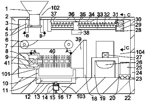
[0022] Combine below Figure 1-5 The present invention is described in detail, and for convenience of description, the orientations mentioned below are now stipulated as follows: figure 1 The up, down, left, right, front and back directions of the projection relationship itself are the same.

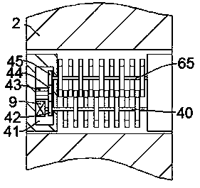
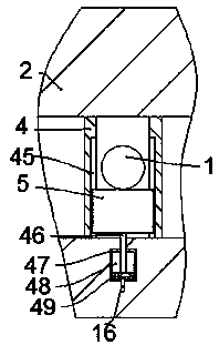
[0023] refer to Figure 1-5 , a mold destruction device according to an embodiment of the present invention, comprising a casing 2, a working chamber 3 is arranged in the casing 2, a first hydraulic tank 47 is fixed in the rear wall of the working chamber 3, and a first hydraulic tank 47 is fixed inside the working chamber 3. The front side of the hydraulic tank 47 is provided with a feeding device 102 for adding the mould. Two groups of belt pulleys 6 are rotatably connected between the front and rear walls of the working chamber 3 below the feeding device 102 . Connected by the belt 7, the top wall of the working chamber 3 on the right side of the feeding device 102 is fixed with a l...


PUM


Abstract

The invention discloses a die destruction device which comprises a shell, wherein a working chamber is disposed in the shell. The die destruction device is characterized in that a first hydraulic boxis fixedly disposed in the rear wall of the working chamber; a feeding device for die feeding is disposed on the front side of the first hydraulic box; two groups of belt wheels are in rotatable connection between front and rear walls of the working chamber under the feeding device; the two groups of belt wheels are connected by a belt; and a left limiting block is fixedly disposed on the top wallof the working chamber on the right side of the feeding device. The die destruction device disclosed by the invention has the beneficial effects that the structure is simple; use is convenient; an iron die and a non-iron die can be screened; the iron die and the non-iron die can be destroyed with corresponding destruction modes, so a recovery rate of materials after destruction can be increased;an electric magnet is made to attract the iron die, and the belt wheels are made to convey a die by the belt in a uniform pace, so omission is prevented.

Description

technical field [0001] The invention relates to the technical field of mold destruction, in particular to a mold destruction equipment. Background technique [0002] As a precision processing equipment, molds include many customers' design patterns and core technologies. Every year, a large number of molds need to be scrapped and destroyed around the world. Mold destruction is usually handed over to a third party for unified processing. If the destruction is not complete, the mold The internal design patterns and core technology may be leaked, and even the molds flow into other companies and be used again, which will bring huge economic losses to customers. [0003] Molds can be made of a variety of materials, commonly divided into iron molds and non-ferrous molds. If molds of different materials use the same destruction method, it will make material recycling more troublesome. At the same time, molds of different materials adopt different destruction methods. . Contents ...

Claims


Application Information

Patent Timeline
IPC IPC(8): B02C4/08B02C4/28F27B14/00
CPCB02C4/08B02C4/28F27B14/00F27B2014/002
Inventor 不公告发明人
Owner 嵊州月明模具科技有限公司
Learn More